
Instruction Manual


DE
DANIELS
ELECTRONICS
MT-3 AM Transmitter Main Board Instruction Manual 4-1
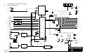
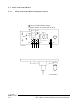
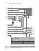
4 TRANSMITTER INTERCONNECT PIN DEFINITIONS
The MT-3 AM series Transmitter employs a 48 pin Eurostandard connector for interfacing to all
transmitter power, audio, and control functions. The following are the MT-3 AM series
Transmitter backplane connections to the M-3 Motherboard.
Pin Name Pin Name Pin Name
D2 N/C B2 +13.8 Vdc Z2 +13.8 Vdc
D4 N/C B4 MIC Out Z4 MIC In
D6 N/C B6 +9.5 Vdc Z6 +9.5 Vdc
D8 N/C B8 Relay Positive Z8 Relay Negative
D10 N/C B10 PTT WTO Z10 PTT WTO
D12 N/C B12 Tx Standby Z12 Tx Standby
D14 N/C B14 PTT NTO Z14 PTT NTO
D16 N/C B16 No Connect (MT-2 +9.5V) Z16 No Connect (MT-2 +9.5V)
D18 N/C B18 Balanced Input 2 Z18 Balanced Input 1
D20 Channel Select 0 (LSB) B20 Squelched,De-emph Audio Z20 Squelched, Flat Audio
D22 Channel Select 1 B22 Subtone Input 1 Z22 Tx Audio Control
D24 Channel Select 2 B24 PTT Output Z24 Subtone Input 2
D26 Channel Select 3 (MSB) B26 Forward Power Sense Z26 Reverse Power Sense
D28 Synth Tx Data (Output) B28 Monitor Out Z28 Direct Mod Input
D30 Synth Rx Data (Input) B30 Ground Z30 Ground
D32 Synth Bootstrap (Input) B32 Ground Z32 Ground