
Instruction Manual

DE
DANIELS
ELECTRONICS
MT-3 AM Transmitter Main Board Instruction Manual 1-1
1 GENERAL
1.1 Introduction
The MT-3 AM Transmitter Main Board integrates the MT-3 Front Panel Board, MT-3 AM Audio
Processor, Synthesizer or Crystal Control module and Amplifier module together to make a
working MT-3 AM series transmitter (see section 5.1: MT-3 AM Transmitter Block Diagram). The
Front Panel Board and the Audio Processor are soldered directly to the Transmitter Main Board
while the Amplifier and the Synthesizer or Crystal Control module are frequency band sensitive,
plug-in modules. Circuitry and jumpers on the Transmitter Main Board control the operation of the
modules as well as the overall operation of the MT-3 transmitter. Power and signal connections are
made to the 48 pin type 'F' connector on the rear of the Transmitter Main Board and are routed to
the other modules. The front and rear back plates are attached to the Transmitter Main Board and
together with the extruded aluminum shell, as discussed in the assembly section of the Transmitter
Manual, form the transmitter enclosure.
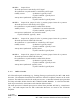
1.2 Performance Specifications
1.2.1 General
Type: MT-3 AM Series Transmitter
Compatibility: VT-3A Series Amplifier, OCT-3 Crystal Oscillator, OST-3
Frequency Synthesizer.
Modulation: 6K00A3 (Amplitude Modulation)
Operating Temperature Range: -30˚C to +60˚C, optional - 40˚C temperature test.
Operating Humidity: 95% RH (non-condensing) at +25°C.
Operating Voltage: +13.8Vdc , +9.5 Vdc Regulated.
Front Panel Control: One 3 position switch
• NORM (repeat mode)
• OFF
• KEY TX
PTT Activation: • Active to ground with or without time-out-timer;
• Microphone activated with or without time-out-timer;
• Front Panel switch: KEY TX - without time-out-timer;
• NORM - with or without time-out-timer.
• Isolated (optional relay) with or without time-out-timer.
PTT Time-Out-Timer: Selectable from 1 sec. to 8 hrs. (factory set 5 min.).