
Instruction Manual

DE
DANIELS
ELECTRONICS
MT-3 AM Transmitter Main Board Instruction Manual 2-3
To configure the isolated input for PTT NTO operation jumpers J2, J4, must be in the 'x' position
J3 must be in the 'y' position. In this mode, pins B14 and Z14 no longer function as the PTT NTO
input; however, pins B10 and Z10 continue to function as the normal PTT WTO input.
2.1.2.5 PTT Output
Pin B24 on the backplane connector is an open drain output (Q9) which is pulled low anytime the
transmitter is keyed and the synthesizer is locked. A crystal controlled transmitter does not have a
locked condition so pin B24 is pulled low anytime the transmitter is keyed. Q9, an N-channel
MOSFET capable of sinking currents up to 2 Amps, is activated by Q8 which is activated by the
Qualified PTT signal (JS2-6) of the synthesizer or crystal control module. The Qualified PTT
signal also controls the LED ENA line for diode D1 on the front panel board and enable line for the
VT-3A Amplifier Module (JP1-1).
2.1.2.6 PTT Voltage Switching
The PTT voltage switching circuitry is comprised of transistors Q1 through Q7 and the associated
resistors. The base of Q1 is driven by the output of U2d which is the combined PTT signal from
all of the PTT inputs. When the transmitter is keyed, Q1 is turned off and subsequently transistors
Q3, Q4, and Q6 are turned on. Transistors Q3, Q4, and Q6 provide three different functions:
•Q3 provides the active low signal for the synthesizer or crystal module PTT input;
•Q4 turns on Q5 which turns on the +9.5 Vdc Switched supply;
•Q6 turns on Q7 which turns on the +9.5 Vdc PTT Switched supply.
The '+9.5 Vdc Switched' supply (Q5) can also be activated by installing jumper J6 or by externally
grounding the TX Standby Line (pins B12 and Z12). The '+9.5 Vdc PTT Switched' supply and
the '+9.5 Vdc Switched' supply both provide +9.5 Vdc but depending on how jumpers J6, J7 and
J18 are configured the transmitter's standby mode will change.
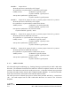
2.1.2.7 Transmitter Standby Modes
The VT-3A130 Transmitter has four different standby modes that trade-off standby current
consumption for start-up speed. The standby modes are determined by three jumpers: jumper J6
which always turns on the '+9.5 Vdc Switched' supply, jumper J7 which selects the power source
for the MT-3 AM Audio Processor and jumper J18 which selects the enable line for the OST-
3A128 Synthesizer or OCT-3 Crystal Control Module.
The actual current and start-up time may depend on the frequncy controlled source (crystal or
synthesizer) and amplifier module. The current and start-up times given below are representative
values intended only as a guideline.