
User Manual


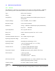


Table Of Contents
- 1GENERAL
- 1.1Introduction
- 1.2Manual Organization
- 1.3VT-4B 136 - 174 MHz Transmitter Family Models
- 1.4Performance Specifications
- 1.4.1General
- 1.4.2Audio Specifications
- 1.4.3Physical Specifications
- 2THEORY OF OPERATION
- 2.1Transmitter Operation
- 2.2Transmitter Programming
- 2.2.1Transmitter Wide Options
- 2.2.1.1Disable Front Panel Led
- 2.2.1.2Secure Hardware Equipped
- 2.2.1.3Allow Emergency Transmissions
- 2.2.1.4Allow Radio Inhibit
- 2.2.1.5Allow Radio Check
- 2.2.1.6Enable Status
- 2.2.1.7Frequency Band
- 2.2.2Channel Wide Settings
- 2.2.2.1Frequency
- 2.2.2.2Voice/Signal Type
- 2.2.2.3Squelch Type
- 2.2.2.4CTCSS Tone
- 2.2.2.5Enable Reverse Burst
- 2.2.2.6DCS Code
- 2.2.2.7DCS Invert
- 2.2.2.8Enable Turn Off Code
- 2.2.2.9Transmitter Power
- 2.2.2.10Channel Bandwidth
- 2.2.2.11Deviation
- 2.2.2.12Time Out Timer
- 2.2.2.13Channel Status
- 2.2.2.14Transmitter Pre-emphasis
- 2.2.2.15NAC Transmitter Code
- 2.2.2.16NAC Transmitter
- 2.3Transmitter Programming using Motorola Radio Service Software
- 2.4Secure Communications
- 2.5Transmitter Assembly and Adjustment
- 2.5.1Controller Board Alignment
- 2.5.1.1Reference Oscillator Adjustment
- 2.5.1.2Transmitter Deviation Balance Adjustment
- 2.5.1.3Transmitter Deviation Limit Adjustment
- 2.5.2Amplifier Alignment
- 2.5.3Frequency Change
- 2.6Recommended Test Equipment List
- 2.7Repair Note
- 2.8Printed Circuitboard Numbering Convention
- 3ILLUSTRATIONS
- 3.1MT-4 Base Transmitter Front Panel
- 3.2MT-4 Transmitter Case - Exploded View
- 3.3Digital Base Transmitter Block Diagram
- 3.4Digital Base Transmitter Schematic Diagram
- 3.5Digital Base Transmitter Main Board Component Layout (Bottom)
- 3.6Digital Base Transmitter Main Board Component Layout (Top)
- 4PARTS LIST
- 4.1P25 Base Transmitter Main Board Parts List
- 4.1.1P25 Base Transmitter Main Board Electrical Parts List
- 4.1.2P25 Base Transmitter Mechanical Parts List
- 5REVISION HISTORY

DE
DANIELS
ELECTRONICS
VT-4B150 VHF Project 25
Digital
Base
Transmitter
Instruction
Manual
2-1
2
THEORY OF OPERATION
2.1
Transmitter Operation
A VT-4B Base Transmitter is constructed using two primary modules: the MT-4 Digital Base
Transmitter Main Board and the VT-4 Amplifier Board. The Main Board supports two plug in
modules: the Transmitter Controller Board and the Transmitter RF Board.
The MT-4 Digital Base Transmitter Main Board receives its audio input through the balanced input
on connector P1, from an external microphone input on connector P1, or from a front panel
microphone. Once on the Main Board, it is immediately digitized using an Analog to Digital
converter.
The digitized signal then passes to the Controller Board, where Digital Signal Processing
techniques are used for volume control, tone signalling, voice compression, filtering, and other
functions. The digital data is then converted to an analog waveform by a Digital to Analog
Converter and passed to the RF board.
On the RF board the signal is used to modulate a RF carrier and then passed to the VT-3 Amplifier
Board for final amplification and transmission.
2.2
Transmitter Programming
The transmitter is programmed with operating frequencies, modulation type, CTCSS and DCS
signalling, and other parameters with the PC-based Radio Programming Software. A special
programming cable is used to connect the serial port of an IBM compatible computer to the Digital
I/O port on the front panel of the Transmitter module. The Radio Programming Software runs
under Window 3.1, Windows 95/98 or Windows NT. Analog test modes may be selected by the
Radio Programming Software, as well as test modes specific to Project 25 digital operation, such
as Bit Error Rate testing.
*** Note that the current version of Radio Programming Software is a demonstration version
only, and cannot be used to program a Transmitter. To program a Transmitter, use Motorola’s
Radio Service Software (RSS), a Motorola Radio Interface Box (RIB), and a Daniels
Programming Cable.
The Transmitter settings are divided into two categories: Transmitter Wide options and Channel
Wide options. When the TX menu is selected from the main screen, both the Transmitter Wide
options and the Channel Wide options for the current channel are displayed. When all Transmitter
Wide and Channel Wide options have been configured in the Radio Programming Software as
required, the radio must have its non-volatile memory updated. The configuration may be saved to
the radio by selecting the TRANSMITTER \ SAVE CONFIGURATION \ TO THE RADIO menu
option. In addition, configurations may be read back from the radio, or saved and read from a file
on the computer by using the TRANSMITTER \ READ CONFIGURATION \ FROM THE
RADIO, TRANSMITTER \ READ CONFIGURATION \ FROM DISK, and TRANSMITTER \
SAVE CONFIGURATION \ TO DISK menu options.