
User Manual


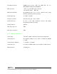
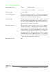
Table Of Contents
- 1GENERAL
- 1.1Introduction
- 1.2Interim Operation
- 1.3Manual Organization
- 1.4VT-4R400 Transmitter Family Models
- 1.5Performance Specifications
- 1.5.1General
- 1.5.2Audio Specifications
- 1.5.3Physical Specifications
- 2THEORY OF OPERATION
- 2.1General
- 2.2Power Supply
- 2.3High Speed Serial Interconnect
- 2.4Audio Circuits
- 2.5PTT Circuitry
- 2.6Microprocessor Board
- 2.7Channel and Bank Selection
- 2.7.1Channel Select Line Mapping
- 2.8Jumper Functions and standard configuration
- 2.9Hang Timer Selection
- 2.10Kerchunk noise selection
- 2.11Test Points
- 2.12Connector Pinouts
- 2.12.1Connector J9
- 2.12.2Connector P1
- 2.13Transmitter Programming
- 2.13.1Transmitter Wide Options
- 2.13.1.1Frequency Band
- 2.13.1.2Source ID
- 2.13.1.3Secure Hardware Equipped
- 2.13.1.4Timeout Options
- 2.13.2Channel Wide Settings
- 2.13.2.1Channel Name
- 2.13.2.2Frequency
- 2.13.2.3Analog Bandwidth
- 2.13.2.4Deviation
- 2.13.2.5Channel Type
- 2.13.2.6Audio Pre-emphasis
- 2.13.2.7Timeout Value
- 2.13.2.8Project 25 Squelch Settings: Network Access Code (NAC)
- 2.13.2.9Project 25 Squelch Settings: Talk Group ID (TGID)
- 2.13.2.10Analog Signaling Settings: Signaling
- 2.13.2.11Analog Signaling Settings: CTCSS Tone
- 2.13.2.12Analog Signaling Settings: Reverse Burst
- 2.13.2.13Analog Signaling Settings: DCS Code
- 2.13.2.14Analog Signaling Settings: Turnoff Code
- 2.13.2.15Analog Squelch Settings: Invert DCS
- 3Transmitter Assembly and Adjustment
- 3.1Frequency Change
- 3.2Minor Frequency Change
- 3.3Major Frequency Change
- 3.4Digital Signal Processor Board Alignment
- 3.4.1Radio Service Software
- 3.4.2Radio Programming Interface Module Interconnection
- 3.4.3Reference Oscillator Adjustment
- 3.4.4Transmitter Deviation Balance Adjustment
- 3.4.5Transmitter Deviation Limit Adjustment
- 3.4.6Audio Level Alignment
- 3.4.7Amplifier Alignment
- 3.5Recommended Test Equipment List
- 3.6Repair Note
- 3.7Printed Circuit board Numbering Convention
- 4Repeater System Configuration
- 4.1Interim Repeater
- 4.1.1Repeater Interconnect Cable Pinout
- 4.2Project 25 Compliant Repeater
- 4.3Repeater System Troubleshooting
- 5ILLUSTRATIONS
- 5.1Digital Repeater Transmitter Front Panel
- 5.2Digital Repeater Transmitter Exploded View
- 5.3Digital Repeater Transmitter Block Diagram (Interim Mode)
- 5.4Digital Repeater Transmitter Schematic Diagram
- 5.5Digital Repeater Transmitter Main Board Component Layout (Bottom)
- 5.6Digital Repeater Transmitter Main Board Component Layout (Top)
- 5.7Digital Repeater Microprocessor Board Component Layout (Bottom)
- 5.8Digital Repeater Microprocessor Board Component Layout (Top)
- 6PARTS LIST
- 6.1Digital Repeater Transmitter Main Board Parts List
- 6.1.1Digital Repeater Transmitter Main Board Electrical Parts List
- 6.1.2Digital Repeater Transmitter Main Board Mechanical Parts List
- 6.2Digital Repeater Microprocessor Board Parts List
- 6.2.1Digital Repeater Microprocessor Board Electrical Parts List
- 6.2.2Digital Transmitter Additional PCBs
- 7REVISION HISTORY

DE
DANIELS
ELECTRONICS
1-4 VT-4R150 VHF Project 25
Digital
Transmitter
Instruction
Manual
1.5.3
Physical
Specifications
Physical
Dimensions:
Width:
Height:
Depth:
7.1 cm
(2.8
in) 12.8 cm
(5.05
in) 19 cm
(7.5
in)
Module
Weight:
1.4 kg
(3.0
lbs.)
Corrosion
Prevention:
Anodized
aluminum
construction. Stainless steel hardware.
Selectively
conformal
coated
glass epoxy 2 and 4 layer printed
circuit
boards.
Gold
plated
module connectors.
Module
Design:
Compact Eurostandard modular design. Plug-in modules
mate
with
Daniels
standard M3
repeater
subrack. Subracks /
modules comply with IEEE 1101, DIN 41494 and IEC 297-3
(mechanical
size / modular arrangement).
External
Connections:
RF
Connection:
type N connector
located
on the
transmitter
module front panel.
Motherboard
Connections (Audio,
Power,
and Control) are made through a 48 pin, gold plated,
type F
connector
on the rear of the
transmitter
module. User
connection
made through
mated
"mother board" assembly of
the
repeater
subrack. Type F standard
connector
complies
with DIN 41612
Level
2 (200
mating
cycles, 4 day 10 ppm
SO2 gas test with no
functional
impairment
and no change in
contact
resistance).
Digital
I/O:
8-pin RJ-45
Handle Text Colour: Red