
User`s manual


15 15
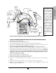
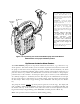
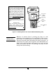
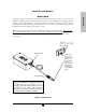
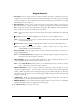
Figure 1.9 Proper installation of the Curlin Medical Administration set into the pump
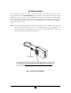
Steps in Installing Administration Set into Curlin Medical Pumps
1 Fully open the door of the pump.
2 Close the slide-clamp on the administration set.
3 Activate the Integral Flow-Stop by twisting and removing the breakaway tab.
4 Insert the blue tubing guide into the receptacle on right side of pump in the direction of the
blue arrow, positioning the tubing in front of the door hinge.
5 Center the tubing in the middle of the pumping fingers, covering the yellow dot.
6 Holding the yellow Integral Flow-Stop by the handle (see Figure 1.9), insert it on an angle into
the receptacle on the left side of the pump in the direction of the yellow arrow. CAUTION:
Do not press down on the top of the Integral Flow-Stop when inserting it into the
receptacle. This action could inadvertently open the Integral Flow-Stop and allow
fluid to flow through the tubing.
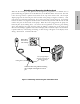
7 Open the slide-clamp on the administration set
8 Push the tubing slightly into the black Air Detector slot.
9 Fully close the door of the pump and latch it securely.
10 If the set is not primed, prime the set according to prime section in the relevant therapy
chapter.
11 Attach the primed set to the patient’s venous access device per agency protocols.
12 Dispose of used administration sets in accordance with all applicable regulatory and
institutional policies and directions.
Introduction
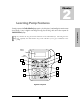
Air Detector
Flow Stop
Handle
(Yellow)
Note: Open the
slide clamp
before closing
the pump door
Tubing
Guide
(
Blue
)
Administration Set
Pumping Fingers
Flow Stop
Rece
p
tacle
Tubing Guide
Rece
p
tacle
Note: The
Administration
Set tubing is
always placed in
front of the door
hinge
Figure 1.9 shows the
Curlin Medical pump
with a cut-away of the
display screen allowing
y
ou to visualize the
receptacles for the
small
blue
“Tubing
Guide” on the right
side of the pump and
the larger
y
ellow
“Integral Flow-Stop”
on the left side of the
p
ump. The arrows, in
corresponding colors,
are visible on the
background surface of
the pump head and
indicate the proper
direction for placing
these locators into their
receptacles. Also, note
that the breakaway tab
has been removed from
the “Integral Flow-
Stop”, allowing the
administration set to be
placed into the pump
correctly.