CA-630 Installation Instructions PROFESSIONAL INSTALLATION STRONGLY RECOMMENDED Installation Precautions: Roll down window to avoid locking keys in vehicle during installation Avoid mounting components or routing wires near hot surfaces Avoid mounting components or routing wires near moving parts Tape or loom wires under hood for protection and appearance Use grommets when routing wires through metal surfaces Use a voltmeter for testing and verifying circuits Technical Support For Authorized Dealers - (8
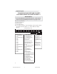
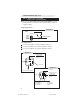
System Layout FOR MODULE FUSE SIZE AND POLARITY LOCATIONS, REFER TO CHART ON PAGE 17. IMPORTANT!!! The module MUST be programmed before it will operate. Refer to the programming instructions on pages 15-18. System Layout CA-630TM A = Advanced Harness B = Basic Harness C = Car Start Harness Note: The wire connection sections will identify each wire with a number (pin cavity) and a letter (harness), i.e.: 20/B = Wire 20, B (Basic) Harness.
1. Basic Harness (B) IMPORTANT!!! • Remove fuses from Module before installation. • Solder and tape all connections. 1/B Parking Light Output +/- (16 AWG) (WHITE) Locate the vehicle parking light wire. Verification: This wire will register either positive voltage or ground when the parking lights are turned on. Voltage does not vary when dimmer switch is adjusted. Refer to the Vehicle Wire Color and Location Chart for the wire color, polarity, and location. Connect the 1/B wire to the parking light wire.
1. Basic Harness (B), cont’d Refer to Diagram 2 to connect to the vehicle’s drivers unlock wire.
1. Basic Harness (B), cont’d Type 3: Negative 3-Wire Door Locking System Polarity Fuse = Negative Single-stage unlock Connect the 2/B wire to the vehicle lock wire. Connect the 14/B wire to the vehicle unlock wire. Two-stage unlock Connect the 2/B wire to the vehicle lock wire. Connect the 24/B wire to the vehicle unlock wire. Use a SPDT relay (not supplied) and refer to Diagram 5 to connect to the vehicle’s driver’s unlock wire.
1. Basic Harness (B), cont’d Type 5: Resistor Door Lock system Polarity Fuse = Positive/Negative Note: Refer to Vehicle Wire Color and Location Chart for correct polarity. Move the fuse inside of the control module to positive or negative polarity. Single Stage Unlock Diagram 7 MODULE WIRES 2 / B Lock 14 / B Unlock Master Vehicle Door Lock Switch or Plunger TO DOOR LOCK MODULE Two-Stage Unlock Connect the 2/B wire as shown in Diagram 7 (above). Connect the 24/B wire as shown in Diagram 8 (below).
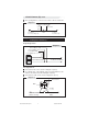
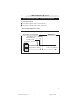
1. Basic Harness (B), cont’d Type 1 (POS) & Type 3 (NEG) 3-wire door lock system Second stage unlock Connect the 2/B wire to the vehicle lock wire. Connect the 13/B wire to the vehicle unlock wire. *Select Polartiy with Fuse Location Type 2 Reverse Polarity Door Lock Systems Type 2 Door Lock Systems Trunk Motor 13/B Diagram 3 Trunk Switch 9/A Lock Motor 2/B Lock Switch 1/A LOCK Vehicle Master Switch To Door Lock Motors UNLOCK 7 CA 630 install revB 8-04.
1. Basic Harness (B), cont’d 3/B Courtesy Light Output +/- (16 AWG) (BLACK/WHITE) Locate the vehicle courtesy light wire. Verification: This wire is usually the door pin switch wire. Refer to testing procedure in 20/B (Pg. 10) to determine the correct polarity of the courtesy light system. Connect wire to the courtesy light wire. IMPORTANT! After installation, set the polarity of this circuit by moving the fuse inside of the control module to positive (+) or negative(-).
1. Basic Harness (B), cont’d. 11/B External Start Trigger Input (20 AWG +/-) (WHITE/BLUE) This wire will activate the Car Start System when a positive/ negative pulse is applied to it from an external device. Refer to option programming IMPORTANT! After installation, the polarity for this circuit must be set in Installer Programming Options /Feature 2 (page 20). 13/B Trunk Release Output +/- (16 AWG) (TAN) Locate the vehicle trunk release wire.
1. Basic Harness (B), cont’d. 20/B Positive/Negative Door Input (20 AWG) (GREEN/VIOLET) Connect the 20/B wire to the vehicle pin switch or courtesy light circuit. Verification - Refer to Vehicle Wire Color and Location Chart for circuit type and location, or verify the vehicle wire using the following guideline: • Positive Systems - Target wire registers voltage when any door is opened. • Negative Systems - Target wire registers ground when any door is opened.
2. Advanced Harness (A) 22/B LED2 (20 AWG+) 23/B LED1 (20 AWG-) Locate a visible section of the dash with 1" clearance behind the location. Drill a 9/32" hole and snap the Status Indicator into place. Connect the Status Indicator Red Wire to the 22/B LED2 wire. Connect the Status Indicator Black Wire to the 23/B LED1 wire. 9/A Trunk Switch 87A (20 AWG) (TAN/RED) This wire is the normally closed pin (87A) for the internal trunk release relay.
3. Car Start Harness (C) 3/C Ignition 2 Output (14 AWG+) (PINK/WHITE) Note: Use the 3/C wire if the vehicle requires connection to a second ignition circuit for the vehicle to operate properly during remote start. Connect this wire to the vehicle second ignition wire at the ignition switch. Connecting To a Third Ignition/ Heater Wire Some vehicles may require connection to more than two ignition or heater wires. If so, use a 30- ampSPDT relay (not supplied), and connect as shown in diagram 12.
3. Car Start Harness (C), cont’d 7/C Brake Input (20 AWG+) (BROWN) Connect the 7/C wire to the vehicle brake light wire. Verification: This wire registers positive voltage when the brake pedal is pressed. 8/C Neutral Safety Switch Input +/- (20 AWG) (BLACK/WHITE) NOTE: The following connections are required to ensure proper operation of the system. Negative systems: Connect the 8/C wire to the vehicle wire at the shifter that will show ground when in park or neutral, and voltage in all other positions.
3. Car Start Harness (C), cont’d 10/C Active Output 500mA (20 AWG -) (BLUE/BLACK) Connect the 10/C wire to add-on relays as described in Diagram 14, or to an optional component requiring a ground signal when the vehicle is running via remote start.
4. System Power-Up and Programming A. System Power-Up 1. All connections must be secure and well insulated. 2. Insert fuses inside of the control module in their respective slots. 3. Replace fuse cover on top of the control module. 4. Turn vehicle ignition on. 5. Plug in 24-pin Basic Harness followed by the 16-pin Advanced Harness and 10-pin Car Start Harness. 6. Turn vehicle ignition off. B.
4. System Power-Up and Programming, cont’d C. Programming Selectable Options Note: Transmitters must be programmed prior to these steps. Press to Turn Press to Restore Feature On/Off Settings to Factory Default Press to Advance to Next Option 1. Repeat steps 1-4 of Remote Transmitter Programming (previous page). 2. Press and release the emergency override button. The horn or siren will sound four (4) times. This indicates that the unit has entered the Keyless Options Programming mode. 3.
4. System Power-Up and Programming, cont’d E. Programming the Tach Signal Note: Skip this step if the vehicle does not have a tach wire or if this unit will be programmed to operate without connection to the tach wire. 1. Open the vehicle hood (hood pin switch must be installed to program tach). 2. Following the steps in Section C (Programming Selectable Options), access Option Bank 4 / Feature 6 (page 18). 3. Start the vehicle with the key, and allow the engine to come to a normal idle.
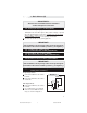
4. Option Programming F. Programming Options Default settings in BOLD OPTION DESCRIPTION Option Bank 0 - 3 Chirps (Learn Transmitters) Option Bank One - 4 Chirps (Keyless Options) 1. Lite TouchAdj. 2. Full Shock Adj 3. IgnitionTriggeredLock 4.
5. System Testing 1. Follow each instruction below. 2. Verify that the CA-630 operates as indicated under each instruction. 3. Check the appropriate wire connections and/or fuses if the unit fails to perform a specific function. Also check that any options pertaining to the function are programmed properly. Remote Start Operation Press START 1. Unit will chirp 4 times if tach is not yet learned or vehicle has not been manually started if in Blind Crank Timing Mode. 2.
5. System Testing, cont’d Start output configuration: Tach Sense Mode If Tach input wire is connected and Tach Sense Mode is enabled, the starter will crank until the tach signal indicates that the vehicle has started, or 4 seconds have passed. After 4 seconds, starter, heater/AC, and ignition will shut off. The unit will pause 5 seconds, then attempt to start the vehicle again. The start sequence will be attempted 4 times before aborting.
5. System Testing, cont’d 3. LED (red light) flashes slowly. Press LOCK twice * If Silent Choice option is set, siren (or horn) sounds twice on second press of LOCK button (once if system is in pre-arm mode). Press UNLOCK 1. Doors unlock 2. Factory alarm (if equipped) is turned off. 3. Courtesy lights turn on for 60 seconds, or until LOCK is pressed or ignition is turned on. Press UNLOCK twice 1. *If Silent Choice Verification is set, siren/horn sounds once. 2.
5. System Testing, cont’d Press START while vehicle is running via Remote Start Defroster (or other device) turns on for 10 minutes or for preset vehicle defrost time. (If the output is connected to another device, the device will activate.) Output will also activate on a single press. Press and hold LOCK Headlights (or other device) turn on for 20 seconds or until LOCK/ LIGHTS is pressed again. (If the output is connected to another device, the device will activate).
9. Mounting the Module / Finishing the Installation IMPORTANT! Perform System Test (page 19-22) before and after this section. 1. Use the supplied long tie wraps to mount the module to a brace or wire harness under the dash. The module and harnesses must be clear of moving parts. 2. Completely uncoil the antenna and route up the nearest front window pillar to the headliner. Be careful not to pinch the antenna under vehicle panels, or route near moving parts. 3.
CA 630 install revB 8-04.