
Programming instructions


10
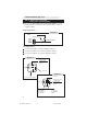
1. Basic Harness (B), cont’d.
86
87
85
30
87a
+12 Volts
21/B
To Horn Wire
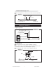
Diagram 10
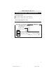
20/B Positive/Negative Door Input (20 AWG) (GREEN/VIOLET)
Connect the 20/B wire to the vehicle pin switch or courtesy light circuit.
Verification - Refer to Vehicle Wire Color and Location Chart for
circuit type and location, or verify the vehicle wire using the
following guideline:
• Positive Systems - Target wire registers
voltage
when any door is opened.
• Negative Systems - Target wire registers ground
when any door is opened.
Important!
After i nstallation, select the polarity of this circuit in programming
Option Bank 4 Feature 1 (factory default = negative), page 18
NOTE:NOTE:
NOTE:NOTE:
NOTE:
FOR POSITIVE SYSTEMS, TEMPORARILY CONNECT THE 20/B WIRE TO GROUND
IN ORDER TO ACCESS THE PROGRAMMING MODE.
CHANGE OPTION BANK 4 /FEATURE 1 TO POSITIVE POLARITY (PAGE 20).
16/B Horn Relay Drive / Siren Output 500mA (BLACK)
Locate the vehicle horn wire.
Verification: This wire will register
either positive or ground when the
horn is pressed.
Connect the 16/B wire to the vehicle
horn wire if the system is negative.
If the system is positive, use a SPDT
Relay (not supplied) and connect the
16/B wire to the vehicle horn wire as
shown (Diagram 10).
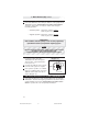
21/B Factory Alarm Disarm Out. (20 AWG-) (BROWN/BLACK)
Connect the 4/A wire to the vehicle anti-theft disarm wire (if equipped).
Verification: This wire will register ground when the driver’s door is
unlocked with the key. Refer to Vehicle Wire Color and Location
Chart for specific wire color and polarity information.
CA 630 install revB 8-04.pmd 8/23/2004, 9:22 AM10