
Programming instructions


11
2. Advanced Harness (A)
22/B LED2 (20 AWG+)
23/B LED1 (20 AWG-)
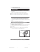
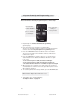
Locate a visible section of the dash with 1" clearance behind
the location.
Drill a
9
/
32
" hole and snap the Status Indicator into place.
Connect the Status Indicator Red Wire to the 22/B LED2 wire.
Connect the Status Indicator Black Wire to the 23/B LED1 wire.
9/A Trunk Switch 87A (20 AWG) (TAN/RED)
This wire is the normally closed pin (87A) for the internal trunk
release relay. If the vehicle has a 5-wire type trunk release it will be
necessary to cut that wire and connect 9/A to the switch side of that
wire.
Note: See 13/B description (Basic Harness).
11/A Rear Defrost Output/Aux 2 500mA (BLUE/WHITE)
Locate the vehicle rear window defrost wire.
Verification: This wire will register either positive voltage or ground
when the rear defroster is turned on.
Connect the 11/A wire to the vehicle defrost wire if the system
is negative.
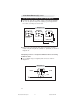
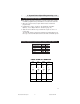
If the system is positive, use a SPDT relay (not supplied) and
connect the 11/A wire as shown (Diagram 11.5).
11/A defrost
wire
+12v fused
Diagram 11.5
86
87
85
30
87a
To vehicle
defrost wire
14/A Armed Output 500 mA (20 AWG -)(ORANGE)
This wire will show a ground when the security system is armed.
CA 630 install revB 8-04.pmd 8/23/2004, 9:22 AM11