
Programming instructions


9
1. Basic Harness (B), cont’d.
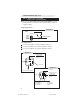
11/B External Start Trigger Input (20 AWG +/-) (WHITE/BLUE)
This wire will activate the Car Start System when a positive/
negative pulse is applied to it from an external device. Refer to
option programming
IMPORTANT!
After installation, the polarity for this circuit must be set in
Installer Programming Options /Feature 2 (page 20).
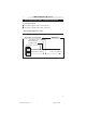
13/B Trunk Release Output +/- (16 AWG) (TAN)
Locate the vehicle trunk release wire.
Verification: Refer to the Vehicle Wire Color and Location Chart
for the wire color, polarity, and location.
Connect the 13/B wire to the vehicle trunk release wire.
Note: If the trunk release system is 5-wire type, refer to wire 9/A
(Advanced Harness Pg. 11).
IMPORTANT!
After installation, set the polarity of this circuit by moving the
fuse inside of the control module to positive (+) or negative(-).
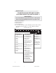
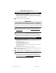
17/B, 18/B Emergency Override Button (20 AWG-)
Find a mounting location for the override button that is not easily
seen or openly accessible. There must be at least 1" clearance
behind the location.
Drill a
9
/
32
" hole and mount the button.
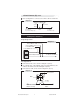
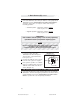
19/B Hood Safety Input (20 AWG -) (GRAY)
Install the supplied pin switch and attach the 19/B wire.
Verification: When connected, the 19/B wire will register ground
when the vehicle hood is opened.
10/B Door Trigger 10K Pull-up Resistor (20 AWG) (YEL/WHITE)
For vehicles with a door input battery saver mode (i.e., Ford Windstar,
Lincoln LS, Cadillac DeVille):
Connect the 16/A wire to a fused constant 12 volt source.
Note: An internal 10k resistor will prevent the door input from going
into battery saver mode to prevent alarm falsing.
CA 630 install revB 8-04.pmd 8/23/2004, 9:22 AM9