CA-640 Installation Instructions PROFESSIONAL INSTALLATION STRONGLY RECOMMENDED Installation Precautions: Roll down window to avoid locking keys in vehicle during installation Avoid mounting components or routing wires near hot surfaces Avoid mounting components or routing wires near moving parts Tape or loom wires under hood for protection and appearance Use grommets when routing wires through metal surfaces Use a voltmeter for testing and verifying circuits Technical Support For Authorized Dealers - (8
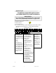
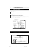
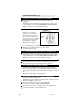
System Layout FOR MODULE FUSE SIZE AND POLARITY LOCATIONS, REFER TO CHART ON PAGE 20. IMPORTANT!!! The module MUST be programmed before it will operate. Refer to the programming instructions on pages 16-21. System Layout Code Alarm CA-640TM A = Advanced Harness B = Basic Harness C = Car Start Harness Note: The wire connection sections will identify each wire with a number (pin cavity) and a letter (harness), i.e.: 20/B = Wire 20, B (Basic) Harness.
1. Basic Harness (B) IMPORTANT!!! • Remove fuses from Module before installation. • Solder and tape all connections. 1/B Parking Light Output (16 AWG) (WHITE) Locate the vehicle parking light wire. Verification: This wire will register either positive voltage or ground when the parking lights are turned on. Voltage does not vary when dimmer switch is adjusted. Refer to the Vehicle Wire Color and Location Chart for the wire color, polarity, and location. Connect the 1/B wire to the parking light wire.
1. Basic Harness (B), cont’d Refer to Diagram 2 to connect to the vehicle’s drivers unlock wire.
1. Basic Harness (B), cont’d Type 3: Negative 3-Wire Door Locking System Polarity Fuse = Negative Single-stage unlock Connect the 2/B wire to the vehicle lock wire. Connect the 14/B wire to the vehicle unlock wire. Two-stage unlock Connect the 2/B wire to the vehicle lock wire. Connect the 24/B wire to the vehicle unlock wire. Use a SPDT relay (not supplied) and refer to Diagram 5 to connect to the vehicle’s driver’s unlock wire.
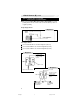
1. Basic Harness (B), cont’d Type 5: Resistor Door Lock system Polarity Fuse = Positive/Negative Note: Refer to Vehicle Wire Color and Location Chart for correct polarity. Move the fuse inside of the control module to positive or negative polarity. Single Stage Unlock Diagram 7 Two-Stage Unlock Connect the 2/B wire as shown in Diagram 7 (above). Connect the 24/B wire as shown in Diagram 8 (below). Connect the 14/B wire as shown in Diagram 9 (below).
1. Basic Harness (B), cont’d 3/B Courtesy Light Output (16 AWG) (BLACK/WHITE) Locate the vehicle courtesy light wire. Verification: This wire is usually the door pin switch wire. Refer to testing procedure in 20/B to determine the correct polarity of the courtesy light system. Connect wire to the courtesy light wire. IMPORTANT! After installation, set the polarity of this circuit by moving the fuse inside of the control module to positive (+) or negative(-).
1. Basic Harness (B), cont’d. 11/B External Start Trigger/ Lite Touch Input (20 AWG +/-) (WHITE/BLUE) This wire will activate the Car Start System or provide an external warn away input when a positive/negative pulse is applied to it from an external device. Refer to option programming IMPORTANT! After installation, the polarity for this circuit must be set in Option Bank 9, Feature 2 (page 20). 13/B Trunk Release Output (16 AWG) (TAN) Locate the vehicle trunk release wire.
1. Basic Harness (B), cont’d. 20/B Positive/Negative Door Input (20 AWG) (GREEN/VIOLET) Connect the 20/B wire to the vehicle pin switch or courtesy light circuit. Verification - Refer to Vehicle Wire Color and Location Chart for circuit type and location, or verify the vehicle wire using the following guideline: • Positive Systems - Target wire registers voltage when any door is opened. • Negative Systems - Target wire registers ground when any door is opened.
2. Advanced Harness (A) 2/A Factory Alarm Arm (20 AWG-) (BLACK/GREEN) Connect the 2/A wire to the vehicle anti-theft arm wire (if equipped). Verification: This wire will register ground when the driver’s door is locked with the key. Refer to Vehicle Wire Color and Location Chart for specific color and polarity information.
2. Advanced Harness (A), cont’d 10/A Cont. Headlight / Aux 1 500ma (20 AWG -) (RED/WHITE) Diagram 11.5 If wire in the vehicle tests positive, use a SPDT relay (not Supplied) and connect as diagram 11.5 as shown +12v fused 10/A Headlight wire or 11/A defrost wire To vehicle headlight or defrost wire 11/A Rear Defrost Output/Aux 2 500ma (20 AWG -) (BLU/WHITE) Locate the vehicle rear window defrost wire.
3. Car Start Harness (C) 14/A Armed Output (20 AWG -)(ORANGE) 500mA This wire will show a ground when the security system is armed. 15/A External Sensor Input (20 AWG -) (BLACK) This wire is a ground input for an external sensor. Connect this wire to the negative output of the external sensor. 2/C Battery (#14 AWG) (RED) Connect 2/C to a main power wire at the ignition switch, preferably to a wire other than the 4/B main power connection.
3. Car Start Harness (C), cont’d 7/C Brake Input / Glow Plug Input (20 AWG+) (BROWN) Connect the 7/C wire to the vehicle brake light wire. Verification: This wire registers positive voltage when the brake pedal is pressed. This wire can be used as a (POS) Glow plug input., diodeisolate if used for both circuits 8/C Neutral Safety Switch (20 AWG) (BLACK/WHITE) NOTE: The following connections are required to ensure proper operation of the system.
3. Car Start Harness (C), cont’d 10/C Active Output (20 AWG -) (BLUE/BLACK) Connect the 10/C wire to add-on relays as described in Diagram 14, or to an optional component requiring a ground signal when the vehicle is running via remote start. Diagram 14 Diodestripeshould face toward InstallDiodesHere 10/C WIRE Note: If you are connecting the 10/C wire to more than one relay, install 1-amp blocking diodes (1N4001 or equivalent) as shown in the Diagram 14.
4. System Power-Up and Programming A. System Power-Up 1. All connections must be secure and well insulated. 2. Insert fuses inside of the control module in their respective slots. 3. Plug in DNA/fuse cover on top of the control module. 4. Turn vehicle ignition on. 5. Plug in 24-pin Basic Harness followed by the 16-pin Advanced Harness and 10-pin Car Start Harness. 6. Plug in 4-pin external antenna receiver into the 4-pin port below the 16-pin Advanced Harness. 7. Turn vehicle ignition off. B.
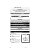
4. System Power-Up and Programming, cont’d C. Programming Selectable Options LOCK UNLOCK Press to Turn Press to Restore Selected All Settings to Feature Factory Defaults FIND/PANIC On /Off Press to Advance to Next Setting Note: Transmitters must be programmed prior to these steps. 1. Repeat steps 1-4 of Remote Transmitter Programming (previous page). 2. Press and release the emergency override button. The horn or siren will sound four (4) times.
4. System Power-Up and Programming, cont’d D. Adjusting the IT-sTM (Interior Theft Sensor) The IT-sTM is factory pre-set at a moderate sensitivity level and has two adjustment points: Lite-Touch and Full Shock. Adjusting Lite-Touch Sensitivity: 1. To program the sensitivity of the lite touch trigger, simply enter into the alarm options bank, then advance to the Lite Touch Adjustment.
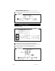
4. System Power-Up and Programming, cont’d F. Programming Options Default settings in BOLD OPTION DESCRIPTION Option Bank 0 - 3 Chirps (Learn Transmitters) Option Bank One - 4 Chirps (Alarm Options) 1. Lite Touch Adj. 2. Full Shock Adj 3. Passive Starter Kill 4. Passive Arming 5. Passive Locks 6. Confirmation Chirps 7.
4. System Power-Up and Programming, cont’d Option Bank Five - 8 Chirps (AUX Options) 1. Auxiliary 1 Adjustment 2. Auxiliary 2 Adjustment 3. Auxiliary 3 Adjustment 4. Auxiliary 4 Adjustment Aux. Adjust Time Table # of Chirps 1 Refer to Table 1.1 ARM Advances to next time Refer to Table 1.1 ARM Advances to next time Refer to Table 1 .1 ARM Advances to next time Refer to T able 1.1 ARM Advances to next time TBL 1.
5. Selectable Coded Override How to use E-Code E-Code is a alternate method of emergency overriding and will take the place of the push-button when selected. The factory preset for this option is 1111 and can be programmed with any combination of numbers 1-9 making sure to use all 4 digits. Programming the 4-digit E-Code: 1. To program a 4-digit code, simply enter into the installer options bank, then advance to the E-Code option (Option Bank 9/Feature6).
6. System Testing 1. Follow each instruction below. 2. Verify that the CA-640 operates as indicated under each instruction. 3. Check the appropriate wire connections and/or fuses if the unit fails to perform a specific function. Also check that any options pertaining to the function are programmed properly. Remote Start Operation Press and hold START for 2 seconds. 1. Unit will chirp 4 times if tach is not yet learned or vehicle has not been manually started if in Blind Crank Timing Mode. 2.
6. System Testing, cont’d Start output configuration: Tach Sense Mode If Tach input wire is connected and Tach Sense Mode is enabled, the starter will crank until the tach signal indicates that the vehicle has started, or 4 seconds have passed. After 4 seconds, starter, heater/AC, and ignition will shut off. The unit will pause 5 seconds, then attempt to start the vehicle again. The start sequence will be attempted 5 times before aborting.
6. System Testing, cont’d 3. LED (blue light) flashes slowly for duration of arm cycle. 4. After 5 seconds, unit monitors all entrances and sensors. Press LOCK, then press FIND/PANIC within 2 seconds to DISABLE the IT-sTM. Two quick chirps verify this function. Pressing LOCK will re-enable shock. Pre-arm mode: 1. The unit will wait for the open door, hood or trunk to be closed. The LED is solid during pre-arm. 2.
6. System Testing, cont’d 4. Courtesy lights turn on for 60 seconds, or until LOCK is pressed or ignition is turned on. 5. Vehicle starter is enabled. 6. LED Flashes if alarm was triggered. Press UNLOCK twice 1. Siren (or horn) sounds once. 2. Passenger doors unlock if using 2-stage unlock. Press FIND Siren/horn sounds 5 times. Press and hold PANIC for 1 second Siren/horn sounds and lights flash for 30 seconds or until any remote control button is pressed.
7. Personalized Transmittter’s A. What is Personalized Transmiiters function This system has the capability to active an auxilary when the unit recieves an unlock command from the tranmitter. This function would be used to activate memory seats or any other device that you wanted activatedwhen unlocked . Option bank 2/Feature 2 (Pg.19) turn festure to the on position (LED ON) Once the option is selected you MUST re-program the transmitters B.
10. Mounting the Module / Finishing the Installation IMPORTANT! Perform System Test (page 22-25) before and after this section. 1. Use the supplied long tie wraps to mount the module to a brace or wire harness under the dash. The module and harnesses must be clear of moving parts. 2. Completely uncoil the antenna and route up the nearest front window pillar to the headliner. Be careful not to pinch the antenna under vehicle panels, or route near moving parts. 3.
CA-640.