Operation Manual CC28 Transmitter for flammable gases and vapours GfG GESELLSCHAFT FÜR GERÄTEBAU MBH▐ KLÖNNESTRASSE 99▐ D-44143 DORTMUND▐ TELEPHONE +49 / (0) 2 31 / 5 64 00 –0 ▐ FAX +49 / (0) 2 31 / 51 63 13 INFO@GFG-MBH.COM ▐ WWW.GASDETECTION.
Content Page For your Safety Operational Hints General Description Detection Principle Design Mounting Position of Transmitter Mounting Installation of Electrical Connections Putting in Operation Detection Mode Check and AutoCal Adjustment of Zeropoint (ZERO) Check and AutoCal Adjustment of Sensitivity (SPAN) Service Menu and Extended Service Menu Sensor Replacement Transmission Characteristics Special Status and relevant Error Messages Messages in detection mode Messages in service mode and during calibrat
For your Safety According to § 3 of the law about technical working media, this manual points out the proper use of the product and serves to prevent dangers. It must be carefully read by all individuals who have or will have the responsibility for operating, using, servicing, maintaining and controlling this product. Like any piece of complex equipment, this product will do the job designed to do, only, if it is operated, used, serviced, maintained and controlled in accordance with GfG’s instructions.
General Description A fixed gas monitoring system consists of a transmitter and a controller (GMA), which are connected by means of cable. The transmitter converts the gas concentration into an electrical signal and transmits it over the cable to the controller for further processing. Compared to the transmitter CC28, the model CC28 D provides an additional display, while the CC28 DA features a display and a visual and audible alarm.
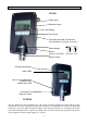
Design CC28 D Cable gland Detection range Display Touch keys Type label with date of production e.g. SN:0504xxxx (05=year, 04=month) Status display Buzzer (only for CC28 DA) green yellow Operation Fault Sensor casing Potential equalization Alarm LEDs Key for quick adjustment (AutoZero key) behind lock screw Connection for Remote Control CC28 DA The type label shows the transmitter type.
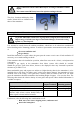
! Always connect the remote control RC2 only for servicing a transmitter without display. The remote control RC2 may be used in explosion endangered areas. They keys, functions and display of the remote control RC2 are identical with those of the transmitter. Mounting Position of Transmitter ! As per EN 50014 table 4 for devices of group II the casing has been tested with an impact energy of 4 Joule (low degree of mechanical danger). Protect the casing against very hard impacts.
The transmitter is to a great extent protected against the ingress of water and dust (IP 64). Special accessories are available to provide additional protection for very difficult conditions. Please contact GfG for detailed information. ! Warranty may be voided, if the sensor is exposed to ambient conditions which were unknown to GfG during planning, production or delivery. Mounting When deciding on the position for the transmitter, make sure that it is always accessible for service and maintenance.
In case the transmitter is not operated on a GMA controller, the operational voltage of the mains unit must not exceed 30 V DC. Fix the casing top with the four special screws after installation. ! The user must make sure that even in case of failure the voltage at the transmitter terminals does not exceed the max. fault voltage Um indicated on the type label. Um = 250 V AC resp.
Detection Mode In detection mode the display shows the current gas concentration. The display reading is always identical with the display of the remote control connected! The detection is provided by continuous monitoring. Exceeded thresholds (only for model CC28 DA) and ambiguous sensor signals are recognized immediately and reported visually by the CC28. Features of the electronics like parameter memory or sensor function are permanently monitored.
Value in “measuring unit” means that the displayed figure stands for either % LEL or Vol.%. Reading in Vol.% applies only to the gas ammonia. Alarm Threshold (only for type CC28 DA) The CC28 DA provides two alarm thresholds. An alarm is triggered, if the gas concentration exceeds the preset limit value (adjustment in service menu). Exceeded thresholds are indicated by means of the LED bar over the display, the display illumination and a buzzer.
A fault of the transmitters is indicated by the constantly lit yellow fault LED, the current interface provides 1.2 mA an error message is shown in the display (SYS ERR. or SENS ERR.). Fault report is given, if: • the sensor or the circuitry in the transmitter is defective; • the sensor is missing; • the self-test of the unit recognizes a failure. For further causes see „Special Status and relevant Error Messages“ on page 21. After the fault is cured, the yellow fault LED expires.
3. After correct entering the display shows alternating the current measurement value and the reading ZERo. When the measurement value remains constant for a defined time interval, the display changes to read ZERo and ADJ for a few seconds, and the hardware internally regulates its zeropoints. Once the regulation is completed successfully, the new zeropoint is set, the AutoCal program is automatically terminated with the display reading SAUE, and the transmitter returns to detection mode.
1. Press key for at least 3 seconds to activate the AutoCal program. During the whole procedure the current interface provides 2.0 mA and, the fault LED flashes slowly. The display shortly reads CodE. and to change the figure at the 2. Now enter the numeric access code 0011. Use keys current position, and confirm by means of key . INFO SPAN TEST ZERO INFO SPAN QUIT MENU 3. After correct entering, the display shows the current measurement value and the message SPAN alternately.
The standard service menu is activated with code 1100 . It allows to adjust the calibration gas concentration and, with model CC28 DA, all values which are related to alarms. The extended service menu is activated with code 5050 . It allows to also change the type of gas, full scale and ambiguity alarm. This code should only be used by specially trained safety personnel. Activation of the extended service menu is only possible, if it has been authorized by GfG during the basic setting of the transmitter.
This function allows to select explicitly all parameters for different types of gas, which are stored in the sensor. You can see only those gases which the sensor is scheduled for. 1. Activate of menu point L MAS. 2. The display shows the presently set type of gas. This reading can also be selscted in the standard service menu. and to set the gas. 3. Use keys In the standard service menu the display shortly reads fAi L and then the presently set type of gas (step 2). TEST INFO ZERO SPAN 4.
In the standard service menu the display shortly reads fAi L and then the current value (step 2). 4. For leaving menu point SCAL press key QUIT MENU briefly. 5. If necessary, store the parameter (SAUE). Notes: The EC-Type Examination Certificate BVS 05 ATEX G 001 X is only valid for a detection range with a full scale of 100 % LEL resp. 4.00 %Vol. NH3. If the full scale value is changed from 100 % LEL to a different value, the function test becomes invalid.
The final reset is only enabled after a zeropoint adjustment has been done with the sensor plugged in. Menu point CL MAS – Adjustment of calibration gas concentration The calibration gas concentration can be set within the range of 10 % – 105 % of the current detection range, but never higher than 85 % LEL. 1. Use key QUIT MENU to select menu point CL MAS . 2. The display reads the currently set value for the calibration gas concentration in % LEL (for ammonia in Vol.%). 3. Use keys 4.
Menu point F1, F2 – Adjustment of alarm functions (only visible at model CC28 DA) 1. Activate menu point F1 resp. F2. 2. The display reads the presently set code for the alarm function. Display NS SC 3. Use keys 4. Press key TEST ZERO QUIT MENU Alarm for exceeded threshold ... non-storing (= non-latching), not resettable (# at alarm 2) storing (= latching), resettable when fallen below and INFO SPAN for setting the parameter. briefly to leave menu point F1 resp. F2 . 5.
Sensor Replacement The sensors MK 208-1, MK 217-1 and MK 218-1 are supplied with an EEPROM which stores the sensor data (serial number etc.), the calibration data and the adjustable types of gases. The sensors are fit to the transmitter by means of a plug connector. For replacing the sensor unscrew the allen screw side-mounted at the impact protection (see picture on page 5 sensor casing). Open the Transmitter casing and use suitable tool to push the sensor downward.
If the transmitter is set to 100%, but the fit sensor had already been used in another unit which was set to 50 % or 75 %, the display will also read CHEC SCAL . Notes: After the sensor was put into operation for the very first time, or when the sensor has been replaced, the transmitter may indicate an overrange resp. underrange (____ resp. ----). In this case the automatic zeropoint adjustment (ZERO) has to be activated to correct the zeropoint. Should SCAL ERR.
Special Status and relevant Error Messages The table below describes those special status which cause the yellow fault LED to be lit permanently. For a better diagnosis of a transmitter without display you should either read the error messages below from the remote control RC2 or analyse the values from the current output. green yellow Output Cause LED LED No Display 01 "TEST" On On "Load" flashing On 02 Operational para.
Messages in detection mode No Display 30 " ---- " green yellow Output LED LED Value " ---- " Value On flashing quickly 22 mA On Off 20–22 mA Overrange (between 100 % and 112 %) On Off 4–20 mA Gas concentration has reached resp. exceeded the 2.alarm threshold. Reduce gas concentration! Latching alarm as standard. On Off 4–20 mA Gas concentration haa reached resp. exceeded the 1.alarm threshold. Reduce gas concentration! Non-latching alarm as standard.
In detection mode the messages listed in the second column are indicated alternating with the measurement value. The readings described in No.33 and 34 are only applicable for model CC28 DA. The readings described in No.35 and 36 are cautionary warning messages. The transmitter remains in detection mode, and there is no immediate action required by the user. The status described in No.32 and 38 refer to a de facto extension of the detection range from 4–20 mA to the range 2.
After installation and during the initial putting into operation gas warning equipment have to be checked for function by an expert (see DIN EN 50073 section 6.4.1) Maintenance comprises inspection, service, calibration and adjustment as well as the regular function tests and repair. A function test has to be effected before putting the transmitter into operation and at least once a year.
Function Restrictions depending on Oxygen Concentration Take note, that the measurement of gas and/or vapour concentrations in the range up to 100 % LEL cannot be done accurately, if simultaneously the oxygen concentration is less than 10 Vol. %. In this case the pellistor suffers from a lack of oxygen necessary for the „catalytic combustion“. The Ex approval is not valid for using the transmitter in oxygen enriched atmospheres with concentrations of more than 25 Vol.% oxygen.
Spare Part List Cap and minor parts for 5 units Casing top screws for 5 units Casing bottom for CC28 Casing top with display for CC28 D and CC28 DA Casing bottom without buzzer for CC28 and CC28 D Casing bottom with buzzer for CC28 DA Main module without alarm (Um=45V) for CC28 and CC28 D Main module without alarm (Um=250V) for CC28 and CC28 D Main module with alarm (Um=45V) for CC28 DA Main module with alarm (Um=250V) for CC28 DA Display module without alarm for CC28 D Display module with alarm for CC28 DA
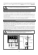
Connection Diagram CC 28 - with 4 ..
Terminal Diagram MWG CC28 3 – wire connection 1 U= 15.0 V - 30.0 V * 2 R1 CC28 3 I = 4 - 20 mA 4 Max. load 150 Ohm 4 – wire connection 1 U= 15.0 V - 30.0 V * 2 CC28 3 R1 I = 4 - 20 mA 4 Max. load 150 Ohm * DC (even short-term voltage peaks) will blow the protective fuse. A voltage exceeding the max.
Sensor specification MK208-1 Catalytic combustion sensor for combustible gases and vapors (according to EN 61779-4) Response time Flow rate Pressure Humidity Temperature Cross sensitivities t50: t90: 0...6m/s: 800...1100 hPa: 5%...90% r.F.: -25...+55°C: at 50%LEL: at 2 %Vol NH3: Special notes: Expected lifetime: ≤ 5 s (CH4), ≤ 5 s (C3H8), *1 with wind protection: ≤ 8 s (CH4), ≤ 8 s (C3H8), *1 ≤ 9 s (CH4), ≤10 s (C3H8), *1 with wind protection: ≤15 s (CH4), ≤17 s (C3H8), *1 max.
Technical Data 3 Transmitter CC28 Transmitter type: Sensor type: Expected sensor life: Gas: Detection range: Response time: Alarm: Detection principle: Gas supply: Supply voltage: Max. supply current: Max. fault voltage: Output current: CC28 ; CC28 D and CC28 DA MK 208-1 ; MK 217-1 and MK 218-1 5 years - for normal industrial applications (see sensor specification) Combustible gases and vapours, e.g. Methane, Propane, Hexane, Nonane (see test report) e.g. 0 ..
Annex Internal Memory CC28 Every transmitter is pre-programmed with the data of the most important gases and their additional parameters. In most cases, therefore, the user does not need to change the configuration.
EC-Type Examination Certificate -34-
-35-
-36-