
Technical data

-21-
Sensor Replacement
The sensors MK 208-1, MK 217-1 and MK 218-1 are supplied with an EEPROM which stores the
sensor data (serial number etc.), the calibration data and the adjustable types of gases. The sensors are
fit to the transmitter by means of a plug connector.
For replacing the sensor unscrew the allen screw side-mounted at the impact protection (see picture
on page 5 sensor casing). Open the Transmitter casing and use suitable tool to push the sensor
downward. The new sensor slides in the casing from below; the sensor label must show forward. The
transmitter provides a lock against rotation, which makes sure that the sensor always fits properly.
Once the sensor is locked in place, secure it with the allen screw. When opening the casing take note
of the safety measures in Ex areas (see page 7).
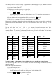
Once the sensor has been removed, the yellow fault LED lights up and the current output signal falls
to 1.2 mA. At model CC28 D and DA the display reads SENS ERR.1 , and at the CC28 DA the alarm
LEDs flash slowly.
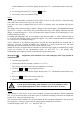
When the new sensor has been fit, the transmitter does an automatic re-start. The display reads RSET
and then TEST (memory test; current output signal of 0 mA). Then the warm-up period is started:
The display reads LoAd , the green LED flashes and the current interface provides an output signal of
1.6 mA. If all data of the new sensor match the stored data for the measurement task, the transmitter
turns automatically from warm-up to detection mode. Since the hardware zeropoints of the different
sensors resp. sensor types may differ considerably, a sensor replacement must always be followed by
a zeropoint adjustment ZERo (see page 11). There are no restrictions for the first zeropoint
adjustment after a sensor replacement. Zeroing is even possible at values far beyond the detection
range (____ resp.
----
).
Possible error messages CHEC LMAS or CHEC SCAL
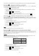
CHEC LMAS During the warm-up period the transmitter recognizes, if the new sensor is not specified
for the gas which is set as the measurement gas. The green LED turns from flashing slowly to a twin
flash (2 short flashes). The yellow fault LED remains lit, the current output still provides 1.6 mA, and
the display reads CHEC LMAS . If the transmitter is to detect that gas which has been set, the sensor is
to be replaced by a cell which is suitable for this gas (e.g. sensor MK 217-1 by sensor MK 208-1).
Should you want to use the new, different sensor anyway (e.g. as a preliminary solution), you may
press key
QUIT
MENU
(longer than 3 seconds) in fault status and enter the acces code 5050 to enter the
extended service menu (see page 14/15); menu point LMAS (appears immediately after the code)
shows the types of gases the new sensor is specified for. If the user selects a type of gas and confirms
his choice by pressing key
QUIT
MENU
, the transmitter is converted to this gas and re-started. Then the
zeropoint ZERo and the sensitivity SPAN have to be set for the new type of gas (see page 11-14).
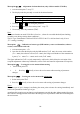
CHEC SCAL New sensors, no matter for which gas, are always pre-set to the detection range of 0 –
100 % LEL. During the warm-up period the transmitter recognizes, if the detection range which was
set last, and the pre-setting of the sensor for the measurement gas do not match. The green LED turns
from flashing slowly to a twin flash (2 short flashes). The yellow fault LED remains lit, the current
interface still provides 1.6 mA, and the display reads CHEC SCAL . For check and, if required,
change of the detection range setting directly from the fault status, you may press key
QUIT
MENU
(longer
than 3 seconds) and enter the code 1100 or 5050 to enter the service mode (see page 14/15), which
allows to do the adjustment under menu point SCAL. After leaving the menu with SAUE the warm-
up procedure is continued.
Example:
If the detection range SCAL was set to 50 % or 75 %, a new and unused sensor will cause the display
to read CHEC SCAL .