
Specifications


35
30
25
20
15
10
5
0
020406080 100 120
3000
2750
2500
2000
2250
1000
1250
1750
1500
750
0
-500 50 100 150 200 250 300 350 400 450 500 550
TEST VALUES
RESISTANCE
Metering pump approx. 10 Ω for 12 volt heater; approximately 36 Ω for
24 volt heater
Glow Pin approx. 0.9 Ω
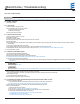
CHECKING THE SENSORS
To check the sensors, measure the resistance at current temperature, see
following diagrams:
TEMPERATURE SENSOR
OVERHEATING SENSOR
Figure 13
TROUBLESHOOTING
BASIC TROUBLESHOOTING
In the event of failure there are several items which should be checked rst
before any major troubleshooting is done.
Check:
• Circuit breakers and fuses.
• Electrical lines and connections.
• For interference in combustion air and exhaust pipes.
• That there is fuel in the tank.
• Battery voltage.
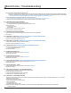
FLAME SENSOR
Figure 14
19
6
Maintenance / Troubleshooting & Repair
REVISION LEVEL A - 12/09/13