
Specifications


PLEASE NOTE!
PLEASE NOTE!
PLEASE NOTE!
SYSTEM OVERVIEW
The Espar Hydronic D5 heater is designed to lower idling by providing an
alternative for engine pre-heat and or cab heat. The Espar Hydronic D5 is also
designed to maintain engine temperature and or cabin temperature. In the
instance cabin temperature is to be maintained, precondition the cab to the
desired temperature is recommended.
SYSTEM OPERATION
1. The operator turns on the device via either an OEM operating control panel,
third party controller, Espar on/off button, switch or an Espar timer to control
the designated start time. The key factor of the control is the fact it sends
power to the heater on the yellow (signal wire).
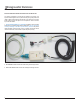
a. In the case the heater does not operate (no fan or
circulating pump), verifying there is output on the yellow wire is imperative.
This can be done by inserting an adapter in the harness (page 6) at the
heater and using a DVM to validate power on the yellow. This should be
close to battery voltage. If there is battery voltage found connect diag-
nostic device (page 4-5) and conrm fault code.
2. The controls options are too many to be listed in this manual but can be
found on the Espar web site, www.espar.com or in your OEM operator’s
manual.
3. When the heater is started the following events take place:
a. The unit runs through a 3 second diagnostic check.
b. The fan, coolant circulating pump and glow pin come on.
c. After 60 seconds the fuel pump starts pumping fuel.
d. If the unit doesn’t re within 2 minutes:
i. The unit will cut the fuel pump and pause for 30 seconds.
ii. The unit will attempt a second start.
e. If the unit doesn’t re within 2 minutes of the restart attempt a code 52
will be set (see code descriptions).
Times are approximate, it is more important to understand there are 2
attempts and the process can takes some time. The unit must be allowed
time to run through its cycle. If there is an issue it will trip a code.
4. Inside the unit
a. The fan provide air ow through the combustion chamber and the
starting air hole
b. The glow pin heats the atomizer chamber in preparation for fuel.
c. Fuel rst enters the atomizer hole.
d. It is then atomized and ignites.
e. The ame burns through the combustion chamber.
f. The ame detector recognizes a temperature rise and cuts operation of
the glow pin.
g. The control unit measures the input and output coolant temperature via
a coolant temperature sensors inserted in the coolant ow of the water
jacket.
This is important to know because the heater can monitor the tempera-
ture difference to validate proper coolant ow. In the case of overheat
codes refer to the appropriate codes.
h. The unit switches between full load, part load and standby automatically
given the coolant temperatures.
i. When it rst ignites it is always in boost.
ii. Mode is controlled via fuel pump frequency and fan speed.
5. Difference in modes
a. When operating in full load the heater will operate at 17,100 BTU to
bring the temperature up. Once the temperature is met it cycles to part
load at 8,200 BTU.
b. If the heater meets 176 F it will cycle to standby mode and extinguish
the ame. The circulating pump will continue to operate so the heater
can monitor and maintain the complete system.
c. If the coolant temperature drops to 167 F the heater will make a repeat
start and repeat the previous steps until it is turned off or faults out.
d. If the heater is completely turned off including the circulating pump and
there is a veried good switch signal then reference the troubleshooting
section of the manual.
After ten no-start attempts the Hydronic 5 ECU will lock to prevent further
startup actions. Until it is veried the ECU is not locked, no repairs should be
attempted on the heater. Because of this, having the proper diagnostic tooling
is a requirement for performing Hydronic 5 repairs.
Figure 5
3
1
System Overview
REVISION LEVEL A - 12/09/13