
Instruction manual

11
Locations and Functions of Parts
Chapter 1 Overview
1-3 Locations and Functions of Parts
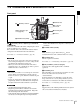
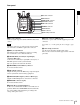
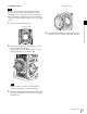
Front panel
a (Network) connector (RJ-45 type, 10BASE-T/
100BASE-TX)
Connects to a network cable when configuring the camera
from a web browser on a computer.
For a network cable connection, the IP address must be
configured in the Network menu in the VF menu.
For details, see “4-2-6 Network Menu” (page 51).
• For safety, do not connect the connector for peripheral
device wiring that might have excessive voltage to this
port. Follow the instructions for this port.
• When you connect the network cable of the unit to
peripheral device, use a shielded-type cable to prevent
malfunction due to radiation noise.
• Par mesure de sécurité, ne raccordez pas le connecteur
pour le câblage de périphériques pouvant avoir une
tension excessive à ce port. Suivez les instructions pour
ce port.
• Lors de la connexion du câble réseau de l’appareil au
périphérique, utilisez un câble blindé afin d’empêcher
tout dysfonctionnement dû au bruit de rayonnement.
• Aus Sicherheitsgründen nicht mit einem
Peripheriegerät-Anschluss verbinden, der zu starke
Spannung für diese Buchse haben könnte. Folgen Sie
den Anweisungen für diese Buchse.
• Verwenden Sie beim Anschließen des Netzwerkkabels
des Geräts an ein Peripheriegerät ein abgeschirmtes
Kabel, um Fehlfunktionen aufgrund von Störungen zu
vermeiden.
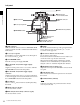
b Ventilation holes (intake)
Make sure that a gap of about 8 mm (
11
/
32
inch) is
maintained in front of the ventilation holes for cooling.
c Viewfinder shoe
Attach an optional viewfinder.
For details, see “2-4 Attaching a Viewfinder” (page 20).
d VF (viewfinder) connector (20-pin)
Connects to the cable supplied with a viewfinder
(optional).
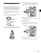
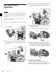
e Lens fixing lever
When mounting a lens, turn the lever clockwise to secure
the lens. To remove the lens, turn the lever
counterclockwise.
If the lens fixing lever is difficult to operate due to the
shape of the lens or accessory being mounted, you can
remove the lever and attach it in a different orientation.
For details, see “2-3 Attaching a Lens” (page 18).
f Hot shoe
Supports the Cooke /i Intelligent Electronic Lens System
and can record lens information as metadata.
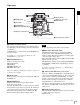
c Viewfinder shoe
Lens mount
a (Network) connector
e Lens fixing lever
d VF connector
f Hot shoe
Shutter emergency open
screw (page 58)
b Ventilation holes (intake)
CAUTION
ATTENTION
VORSICHT
Note