
Instruction manual

13
Locations and Functions of Parts
Chapter 1 Overview
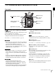
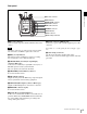
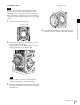
Right panel
a ASSIGN (assignable) buttons
You can assign various functions to these buttons, using
the subdisplay or the menu displayed in the viewfinder or
on a monitor.
ASSIGN button 1 is on the far left, and ASSIGN button 4
is on the far right.
For details, see “3-3-13 Assigning Functions to the
ASSIGN Buttons” (page 32).
b DIAGNOSIS indicator
Indicates the diagnostics status.
Lit green: Normal
Lit red: Error
Flashing red: Fatal error
Lit yellow: Not ready
If the red or flashing red indication continues, consult your
local Sony representative.
c LOCK switch
Locks operation of the side panel (excluding the REC and
PAGE buttons).
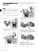
d SHUTTER button
Switches between the electronic shutter and the
mechanical rotary shutter.
Press the “M.” button for one second or longer to switch to
the mechanical rotary shutter, or press the “E.” button for
one second or longer to switch to the electronic shutter.
The button indicator for the selected shutter is lit. The
shutter indicator flashes when changing shutter.
It takes about 20 to 40 seconds to change shutter.
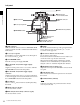
e REC button and LOCK switch
The REC button starts/stops recording to the SR-R4
docked on the camera. The REC button indicator is lit
while recording. The indicator flashes as a warning if the
connected supply voltage drops.
When the LOCK switch is in the LOCK position, the REC
button cannot be operated.
The REC button cannot be operated during REC REVIEW,
PLAY, F.FWD, or REW mode on the SR-R4 to prevent
overwriting.
For details on warning indications, see “Warning/Error
Messages” (page 56).
f “Memory Stick”/SD memory card section
Slots for a “Memory Stick PRO Duo” and an SD memory
card are provided behind the rubber cap. The access lamp
turns red when a “Memory Stick PRO Duo” or an SD
memory card is inserted into a slot, and then turns off. It
flashes red when reading to or writing from a “Memory
Stick PRO Duo” or an SD memory card.
When the access lamp is flashing red, do not insert/remove
the “Memory Stick PRO Duo” or SD memory card, or turn
off the power.
g DOCK (docking) indicator
When an SR-R4 is docked, the light reception status of the
recorder connectors is displayed.
Green: Good
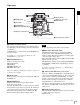
b DIAGNOSIS indicator
c LOCK switch
d SHUTTER button
h Tripod receptacles (bottom)
Display/menu operation block
f “Memory Stick”/
SD memory card section
a ASSIGN buttons
e REC button and LOCK switch
g DOCK indicator
Note