
Instruction manual

15
Locations and Functions of Parts
Chapter 1 Overview
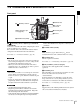
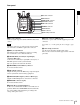
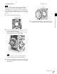
Rear panel
a Recorder connector
Connects signal and power with the SR-R4 docked on the
camera.
Attach the connector cap on the optical connector when
not connected to an SR-R4 to protect the connector.
b REC (record) indicator
The indicator is lit red while the recorder is recording.
You can slide the cover to hide the indicator.
c GENLOCK IN (external sync signal input)
connector (BNC type)
Connects to an external sync signal (HD 3-level sync) or
HD-SDI signal for camera synchronization.
The sync signal is selected in the VF menu.
d SHUTTER (external shutter) connector
It is not used in this version.
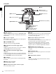
e HD-Y OUT connector
Outputs the Y-signal for the HD analog component signal.
Used to synchronize external analog equipment.
f SDI OUT1 (SDI output 1) connector (BNC type)
Outputs an HD-SDI signal for connection to a monitor.
g REMOTE connector (8-pin)
It is not used in this version.
h DC IN (DC power input) indicator
A 10.5 V to 17 V indicator and 20 V to 30 V indicator are
provided. When the CAM POWER switch is turned ON,
the corresponding indicator lights up according to the
voltage of the power source.
i DC IN connector (LEMO 8-pin)
Connects to a power cable with the supplied power cable
connector.
For details, see “2-7 Preparing the Power Supply” (page
22).
j Cable clamp screw holes
Can be used to attach the supplied cable clamp.
There are also screw holes on the upper surface on the left
panel side.
f SDI OUT1 connector
g REMOTE connector
h DC IN indicator
i DC IN connector
e HD-Y OUT connector
b REC indicator
c GENLOCK IN connector
a Recorder connector
d SHUTTER connector
j Cable clamp screw holes
Note