
Instruction manual


37
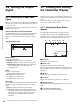
Viewing and Setting the Viewfinder Display
Chapter 3 Basic Adjustments and Settings
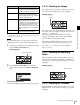
g Look-up table (LUT)
Displays the file name of the look-up table currently
selected.
h Recording status indicator
Displays “z” when the SR-R4 docked on the camera is
recording.
i Media remaining
Displays the approximate number of minutes remaining
for the recording media in the SR-R4 docked on the
camera.
j Power supply voltages
Displays the state of the output voltages. The output from
DC 24 V OUT is displayed on the left, and DC 12 V OUT
on the right.
The voltage readout begins to flash if the corresponding
input voltage falls to the Near End value specified on the
<Battery Alarm> page in the Config menu. The indicator
flashes more rapidly if the voltage falls to the End value.
k Message area
Displays a warning/error message if an error occurs. The
error details are also displayed in the self diagnostics field
in settings page 3 on the subdisplay.
For details about messages, see “Warning/Error
Messages” (page 56).
3-7-2 Setting the Marker Display
Various markers can be displayed in the viewfinder and on
the monitor.
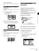
Turning status/marker display On/Off for
each output
You can set whether to display status information and
markers in the signal output from the VF and SDI OUT
connectors on the <Mix> page in the Display Info menu
(page 46).
<Mix> page
The default setting is to display status information and
markers in the signals from the VF and SDI OUT
connectors.
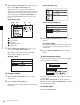
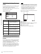
Specifying the markers to display
When the marker display is turned On on the <Mix> page,
you select the markers for display on the <Marker> page in
the Display Info menu.
<Marker> page
The default setting for all markers is “Off.”
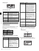
Item Setting
[Status/Menu] VF Sets whether to display status
information in the VF connector
signal.
SDI Sets whether to display status
information in the SDI OUT
connector signal.
Status Size Sets the text size for status
information.
[Marker] VF Sets whether to display markers in
the VF connector signal.
SDI Sets whether to display markers in
the SDI OUT connector signal.
Color Sets the display color of markers.
Brightness Sets the marker display brightness in
the range 1 to 10 (maximum
brightness is 10).
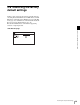
Item Setting
Center Marker Sets whether to display the center
marker.
Effective Sets whether to display the effective
pixel area.
Aspect Ratio Selects the aspect ratio when Effective
is set to On. The following options are
available.
2.39:1, 2.35:1, 1.90:1, 1.85:1, 1.78:1,
1.66:1, 1.33:1, Variable
Width Specifies the width of the effective pixel
area (960 to 1920 pixels) when Aspect
Ratio is set to Variable.
Height Specifies the height of the effective pixel
area (540 to 1080 pixels) when Aspect
Ratio is set to Variable.
Ratio (Variable) Displays the aspect ratio in n.mm:1
format when Aspect Ratio is set to
Variable.