
Technical data
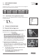


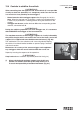


13.2 Manual extension and re-entry of the outrigger supports
(!) ATTENTION (!)
To manoeuvre the supports hands must only grab the handles placed on the
outrigger rams.
- Disengage the locking devices of the outrigger supports by
putting the levers of the devices A and B from the position of
the fig. 8 to the one of the 8a.
- Pull, extending from the base the outrigger support.
- Position the lever of the device B downwards; the locking loaded
security device B remains disengaged.
- Pull, extending the outrigger support till the engaging of the
pin of the device B in its seat.
- By the same sequence, repeat the operations described to
extend the other support.
(!) ATTENTION (!)
The engaging of the outriggers lock B ensures the complete extension
of the outrigger support (essential for the stability of the complete
crane vehicle unit) and the impossibility of accidental movement.
(!) ATTENTION (!)
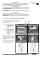
The complete extension of the outrigger support is visually indicated
by the yellow triangle which is found at the end of the beam. (fig. 8b)
To re-enter the outriggers repeat the operations previously described
in reverse.
(!) ATTENTION (!)
Keep hands clear of automatic stop device (lever A of the fig. 8).
Always check that the outriggers locks, once in their rest position, are
locked in their seat by the safety devices, so as to assure the impossi-
bility of accidental movement.
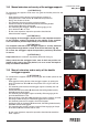
13.3 Manual extension and re-entry of the double
outrigger supports
(!) ATTENTION (!)
To manoeuvre the supports hands must only grab the handles placed on the
outrigger rams.
- Disengage the locking device of the outrigger supports by putting the
levers of the devices A and B from the position of the fig. 9 to the one
of the 9a.
- Pull, extending from the base the outrigger support assembly (first and
second support).
- Position the lever of the device B downwards; the locking loaded security
device B remains disengaged.
- Pull, extending the outrigger support assembly, till the engaging of the
pin of the device B in its seat.
- Rotate the lever of the device B1 positioned on the first support, upwards;
the spring loaded security pin will be disengaged from it’s position.
- Pull, extending from the first support, the second support.
- Position the lever of the device B1 downwards; the locking loaded security
device B1 remains disengaged.
- Pull, extending the second outrigger support till the engaging of the pin
of the device B1 which locates into its seat.
- By the same sequence, repeat the operations described to extend the
other supports.
13.2
SUPPLEMENTARY BEAMS
GR2_60»65
A
B
A
B
A
fig. 8a
fig. 8
fig. 8b
B
A
B
B1
fig. 9
fig. 9a