
Technical data

16.2
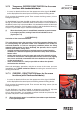
CONTROLS TO
OPERATE THE CRANE
GR2_45»65_3_4_SE
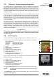
16.2 "Electronic" lifting moment limiting device
This device utilises an electro-hydraulic system managed by an electronic
logic that prevents any operation tending to cause an increase in the pressure
induced by the load in the lifting rams (inner, outer rams of the crane and of
the hydraulic extension, if fitted), up to the critical values. These values, which
are not exceedable, determine the intervention levels and provide the data for
setting the device.
The pressure values detected in the lifting rams are turned into electric signals
by the transducers, and sent to the electronic logic of the device which deter-
mines the locking or unlocking of the controls concerned, according to the
horizontal position of the crane outer boom (mercury level switch); only the
controls allowing a reduction of the overload are enabled, while those increa-
sing it are disabled.
The device features an electro-hydraulic control that does not allow the set
value to be exceed, by deactivating the controls (levers in neutral position)
commanded by the limiting device. When the controls are released (levers in
neutral position) it's this electronic logic that handles which manoeuvres are
disabled, according to the position of the crane outer boom and in overload
condition, by sending electric signals to special micro-switches placed on the
elements of the distributor.
(!) ATTENTION (!)
The presence of the lifting moment limiting device does not release the
user from the obligation to respect what is indicated on capacity plates
and lifting curves.
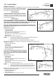
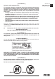
16.3 Control panels
Layout of the control panel (fig. 17), placed next to the distributor of the crane
A - green, yellow and red led band signalling the load percentage as compared
to the capacity plate
Green light load between 0 and 90%
Yellow light load between 90 and 100%
Red light load higher than 100%
B - Display
C - Control buttons (4 control buttons)
D -
“STOP” button
E -
Audible alarm push button (danger)
F - Green warning light (electric on)
G - Control button for XP
H - Control button for the temporary exclusion
of the lifting moment limiting device
Layout of the control panel (fig. 18) (if fitted) placed on the double control side and
on top seat (version with hand-cable controls)
D -
“STOP” button
E -
Audible alarm push button (danger)
F - Green warning light (electric on)
G - Control button for XP
H - Control button for the temporary exclusion
of the lifting moment limiting device
If the green warning light F comes on, it confirms that the electric circuit is active.
!NOTE! In the absence of electric power all crane functions will be
desactivated.
If the yellow led A comes on during load handling, 90% of the capacity (lifting
moment) has been reached.
fig. 17
fig. 18
A
B
C
H
D
C
G
F
E