
Technical data
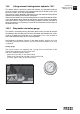
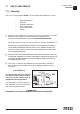
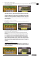

3. Message “M1 - M2 - M3” (fig. 3)
After having pressed the above mentioned keys, the message illustrated in
Fig. 3 will be displayed.
At this point, through the "+" button, select the correct number of the manual exten-
sion at the moment in use (M stands for manual and 1, 2 and 3 indicate the number
of the manual extensions). Select the number of the manual extension you want; that
number starts blinking. You can select only the manual extensions that have been
installed: i.e. if only one manual extension is installed, by pressing the "+" key, only the
M1extension will start flashing. To confirm your choice, press once the “F1” key (control
panel) or “ENTER” (radio-remote control); you'll access the section dedicated to the
system configuration.
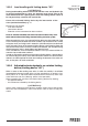
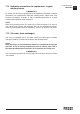
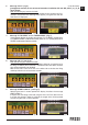
4. Message “K1 - K2 - K3 - K4” (fig. 4)
[paragraph to read only in case of manual extensions installed on Jib and
not on Crane]
If you press the "ENTER" key with the manual extensions mounted on the
jib, the screen of Fig. 4 will be displayed.
Therefore we can choose the most convenient configuration among the
following:
K1 Outer booms of the crane totally re-entered and jib extensions as you like
K2 Outer booms of the crane as you like and jib extensions totally re-entered
K3 Outer booms of the crane totally extended and jib extensions as you like
K4 Outer booms of the crane as you like and jib extensions totally extended
Select the desired configuration using the * button to move among the various
options. Confirm your selection by pressing the “F1” (control panel) or “ENTER”
(radio-remote control) key. If the hydraulic jib boom is not at its stroke end, the
message at point 3 will be displayed; otherwise the message "F1 TO START" is
visualised.
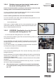
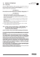
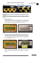
5. Message “FC P2” (fig. 5)
Note: do not hang any load on the hook.
This means that the outer ram must be positioned at its stroke end (if it is
already in that position this message won't appear), using the lever until the
next screen is displayed.
18.2
USE OF IMPLEMENTS
GR2_45»65_3_4_5_SE
fig. 3
fig. 3
fig. 4
fig. 4
fig. 5
fig. 5