
Technical data
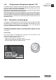
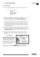
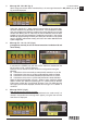

6. Message “FC P3” (fig. 6)
[paragraph to read only in case of manual extensions installed on Jib and
not on Crane]
Note: do not hang any load on the hook.
This means that the jib outrigger must be positioned at its stroke end (if it is
already in that position this message won't appear), using the lever until the
next screen is displayed.
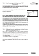
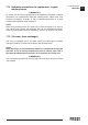
7. Message “F1 TO START” or “F1 / ENTER START” (Fig. 7)
At this point the display will visualize the message "F1 TO START" (control panel)
or "F1/ENTER START" (radio-remote control). Press the "F1" (control panel) key or
"ENTER" (radio-remote control) to continue.
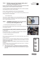
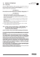
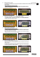
8. Message “UP P1” (see fig. 8)
Note: do not hang any load on the hook.
It requires the activation of the inner boom lifting to eliminate an overpressure at
the lifting ram bottom (the manoeuvre is activated but the crane does not move
since all the movements are disabled).
Note: set the lever of the inner ram at its stroke end to simulate the lifting
and keep it like this for at least three seconds.
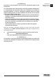
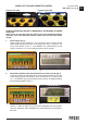
9. Message “START LOAD P1” (see Fig. 9)
Releasing the lever in neutral position the display visualises the message
START LOAD P1.
It requires the slow lifting of the load using the inner ram. This allows to haul
it up from the ground in order to calculate the weight which will be pointed
out releasing the lever in neutral position.
18.2
USE OF IMPLEMENTS
GR2_45»65_3_4_5_SE
fig. 6
fig. 6
fig. 7
fig. 7
fig. 8
fig. 8
fig. 9
fig. 9