
Troubleshooting guide
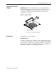
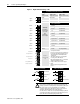
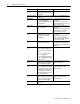
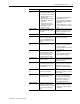
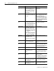
Table Of Contents
1336 PLUS - 6.16 - September, 2001
Control Logic Wiring and Adapters 2-3
Control Interface Board
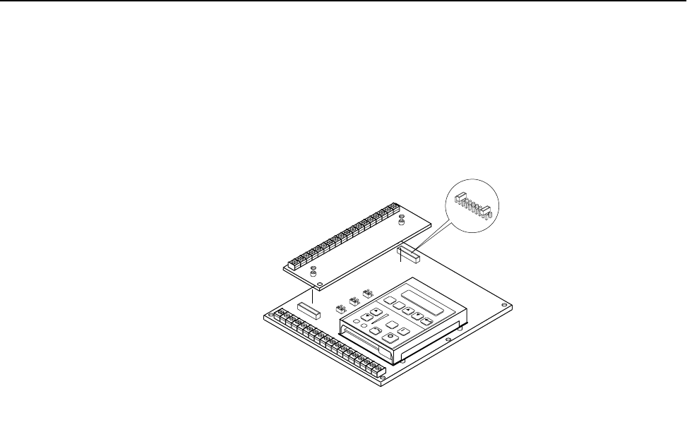
Jumpers
IMPORTANT:
If the Control Interface Board is being installed, Main
Control Board Jumpers at pins 3 & 4 and 17 & 18 of J2 must be removed
and the proper [Input Mode] selected. If this board is removed, these
jumpers must be reinstalled and the [Input Mode] parameter must be
programmed to “Status (1).”
Figure 2.2 Jumper Locations
Digital Inputs
Digital Inputs are connected at TB3.
Input Mode Select
A number of combinations are available by first programming [Input Mode]
to the desired control scheme (i.e. 2 wire, 3 wire or Status). The remaining
inputs can then be configured by programming [TB3 Term 22 Sel] through
[TB3 Term 28 Sel]. Refer to the Digital I/O parameter group in Chapter 6 of
the PLUS II User Manual for programming information.
J2
Frames
1
A1 - A4
1
Refer to page 1–1 for frame reference classifications.
JOG
ES
C
S
E
L
J11
J8
J13