
Troubleshooting guide
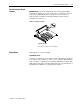
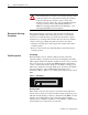
Table Of Contents
Chapter
3
Troubleshooting and Error Codes
Chapter Objectives
This chapter helps you trace faults to field-replaceable components.
NOTE: On 1336 PLUS II A1 - A4 Frames, the only replaceable parts are the
Main Control Board and Fans.
Troubleshooting Overview
To troubleshoot a 1336 PLUS II Adjustable Frequency AC Drive, you need
a Range DVM, or VOM with a range capacity of at least 1000V.
IMPORTANT: All printed circuit boards, except the Main Control Board
assembly, are referenced to negative ground (-bus).
!
ATTENTION:
Power circuits are optically isolated from
control driver circuits. Power circuit components are “floating”
with respect to “ground”. Use only approved methods of
isolating test equipment when making measurements in power
circuits.
ATTENTION:
Some printed circuit boards and drive
components may contain hazardous voltage levels. Remove
power before you disconnect or reconnect wires, and before you
remove or replace fuses and circuit boards. Verify bus voltage by
measuring the voltage between +DC and -DC on Terminal Block
TB1. Do Not attempt to service the drive until the bus voltage has
discharged to zero volts.
ATTENTION:
Potentially fatal voltages may result from
improper useage of oscilliscope and other test equipment. The
oscilliscope chassis may be at a potentially fatal voltage if not
properly grounded. We do not recommend use of an oscilliscope
to directly measure high voltages. Use an isolated measuring
device with a high voltage probe. Contact Allen-Bradley for
recommendations.
ATTENTION:
To guard against equipment damage when
troubleshooting the drive, always check the following before
issuing a Start command:
–
Set the Speed Reference to minimum.
–
Select the proper motor-rotation direction.
–
Disconnect the motor from its mechanical load.