FILE NO. SERVICE MANUAL Real Time Video Cassette Recorder SRT-8960P (Product Code : 175 700 72) (Europe) SRT-8960P (Product Code : 175 700 88) (U.K.) SRT-8040P (Product Code : 175 700 73) (Europe) SRT-8040P (Product Code : 175 700 89) (U.K.) CONTENTS MAINTENANCE TABLE ON THE MONITOR SCREEN ........... 3 1. DISASSEMBLY .................................................................... 6 2. ELECTRICAL ADJUSTMENT ............................................ 10 3. TEST POINTS FOR TAPE PATH ADJUSTMENT .
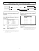
MAINTENANCE TABLE ON THE MONITOR SCREEN To display the maintenance table, press “MENU” key with “ POWER FAILURE Normal screen ” key while the fourth MENU is displayed. Press “MENU” key with “ “MENU” key “MENU” key Maintenance table 2 As shown in Fig. below Maintenance Table 2, is displayed on the screen. The used time of each mode (part) is displayed, and can be reset by items. Access the maintenance-screen according to the above, and then Fig. below is displayed.
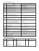
Error Codes (Self-Diagnosis Contents) No. Mechanism Operations and State After Occurrence Problem E01 The cylinder does not rotate. The tape winds around the cylinder. Shift to the STOP mode. Unload forcibly. E02 The take-up reel does not rotate. Shift to the STOP mode. E03 The capstan motor does not rotate. Shift to the STOP mode. E04 The tape can not be loaded. (But unloading can be performed.) Unload, shift to the ST-BY mode, and the power goes off.
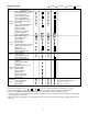
Maintenance Table : Cleaning 2000H 4000H ASSY, BRAKE BAND ASSY, LEVER BT (tape guide) FULL ERASE HEAD ASSY, ROLLER CLEANER ASSY, GUIDE ROLLER ASSY, MOUNTING INCLNE S ASSY, MOUNTING INCLNE T Tape path ACE HEAD system ASSY, LEVER PINCH ROLLER MOUNTING, LIFT PINCH CAM, LIFT PINCH GEAR, CAM PINCH EARTH CHIP CYLINDER COMPL, CYLINDER ASSY, CYLINDER UPPER ASSY, REEL SUPPLY ASSY, REEL TAKEUP GEAR, REEL S GEAR, REEL T Reel drive PULLEY, REEL system SPECIAL, WASHER 2.4 X 6 X 0.
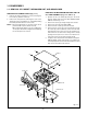
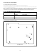
1. DISASSEMBLY 1-1. REMOVAL OF CABINET, MECHANISM UNIT, AND MAIN BOARD REMOVING THE MECHANISM MAIN UNIT AND THE CP-1 PWB ASSEMBLY (Fig. 1-1-2 and 1-1-3) REMOVING THE CABINET PARTS (Fig. 1-1-1) 1. Remove the cabinet and bottom cover by removing the four screws (1) and five screws (2). 2. Remove the front panel by removing the locks of the clamps (A) using a screwdriver, etc. and slightly rotating the bottom part in the direction of the arrow.
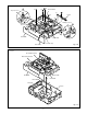
M-RQ4Q/EX-2 A (7) (8) (4) Tray Lock Lever Terminal Board (5) (7) Holder (8) (3) Lid Opener Lever Chassis B (B) (B) (B) (B) (B) (B) (6) (B) (C) TM-1 PWB (C) (C) PW-1 PWB Cassette Tray TM-2 PWB Fig. 1-1-2 M-RQ4Q/EX-3 CP-1 PWB Assembly Mechanism Main Unit TM-1 PWB PW-2 PWB PW-1 PWB TM-2 PWB Clamp(D) Chassis Fig.
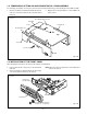
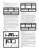
1-2. TEMPORARILY SETTING UP AND CONNECTING CP-1 PWB ASSEMBLY The following is an example of how to place and connect the main board without a jig, when repairing the CP-1 PWB assembly. 1. 2. Place the mechanism unit and main board up side down as a whole on a flat surface with foil side of the main board facing up. M-RF4QR/NA-4 Operete the unit using the buttons on CP-1 PWB or the remote control.
1-4.
2. ELECTRICAL ADJUSTMENT 2-1. SERVO CIRCUIT ADJUSTMENT • These adjustments should be carried out upon completion of the tape transport adjustments. • If the tape transport adjustments (except the tilt adjustment) are done after these adjustments, follow the procedures again in section 2-1-3. “SWITCHING POSITION ADJ.” • When a cassette tape is loaded, auto-tracking will be set immediately after starting the first playback.
2-1-4. 24H PLAY TRACKING CONFIRM AND ADJ. Notes : • Set the REC/PLAY SPEED button to indicator panel to the 8 H (8 hours) mode. • Self-recoding means “Record any broadcasting or video signal and play back the just-recorded portion”. Measuring Point Measuring Equipment Adj. Condition Picture of monitor TV 2-1-3. SWITCHING POSITION ADJ. Measuring Point Measuring Equipment Adj. Condition TP101(VIDEO OUT terminal) TP183 (SW-P) Oscilloscope Adj. Location 6.5 H ± 0.5 H 1. Play back the alignment tape.
2-2. VIDEO CIRCUIT ADJUSTMENT Before making the following adjustments, complete the adjustments described in section 2-1. “Servo Circuit.” 2-2-1. TEST EQUIPMENT AND STANDARDS REQUIRED Color Bar Signal Generator PAL color bar signal with 100% white level, monoscope signal Oscilloscope Vertical sensitivity Bandwidth Blank Tape VHS cassette tape Alignment tape VHJ-0008 : 5 mV/DIV, external trigger : more than 10 MHz : SP mode, color bar, 1 kHz 2-2-3. 2H DELAY LEVEL ADJ.
4. PARTS LIST Destination SRT-8960P : SRT-8960P (Europe) SRT-8960P-UK : SRT-8960P (U.K.) SRT-8040P : SRT-8040P (Europe) SRT-8040P-UK : SRT-8040P (U.K.) LOCATION PARTS NO. DESCRIPTION ACCESSORIES & PACKING MATERIALS 9170 9205 613 197 8966 645 045 3533 9205 OR 9211 9001 9001 9001 9001 9002 9003 9010 645 009 0400 613 095 0550 613 133 1907 613 197 8928 613 198 2857 613 198 8330 613 198 8347 613 196 6680 613 196 6697 645 044 2797 INSTRUCTION MANUAL CORD,POWER-1.8MK, SRT-8960P-UK,SRT-8040P-UK CORD,POWER-1.
LOCATION PARTS NO.
LOCATION 50700 50800 50900 51000 51010 51100 51200 51300 6090A OR 6090B 6090C 60910 61000 61100 7010A 7010B 7010C 70200 70300 70400 70410 8010A 8010B 80200 80300 PARTS NO.
ELECTRICAL PARTS Note: 1. Materials of Capacitors and Resistors are abbreviated as follows ; Resistors Capacitors MT-FILM Metallized Film Resistor MT-POLYEST MT-GLAZE Metallized Glaze Resistor MT-COMPO OXIDE-MT Oxide Metallized Film Resistor TA-SOLID AL-SOLID NP-ELECT OS-SOLID 2. 3. 4. 5.
LOCATION Q1301 OR Q1306 OR OR Q1307 OR OR OR Q1321 OR OR Q1322 OR OR Q1323 OR OR Q1324 OR OR Q1341 OR OR Q1341 Q1342 OR OR Q1343 OR OR Q1344 OR OR Q1401 OR OR OR Q1420 OR OR Q1421 OR OR Q1422 OR OR Q1431 Q1432 Q1433 Q1434 Q1435 Q1436 Q1437 Q1461 OR OR Q1462 OR OR OR Q1471 OR OR Q1472 OR OR OR Q1481 OR OR OR Q1491 Q1601 Q1602 OR OR Q1603 PARTS NO.
LOCATION IC121 IC131 IC132 IC141 IC142 IC143 IC145 IC161 IC211 OR IC301 IC302 IC303 OR IC304 IC305 OR OR IC306 IC308 IC309 PARTS NO.
LOCATION C1010 C1011 C1012 C1013 C1014 C1015 C1031 C1032 C1033 C1034 C1035 C1036 C1037 C1038 C1039 C1041 C1042 C1043 C1045 C1046 C1047 C1048 C1049 C1050 C1051 C1052 C1062 C1067 C1068 C1075 C1081 C1088 C1101 C1110 C1121 C1122 C1123 C1139 C1151 C1152 C1153 C1154 C1155 C1201 C1202 C1210 C1211 C1213 C1221 C1222 C1223 C1224 C1225 C1226 C1227 C1228 C1229 C1230 C1231 C1233 C1234 C1235 C1236 C1238 C1241 C1242 C1251 C1253 C1254 C1255 C1256 C1257 C1301 C1302 C1303 C1304 C1305 C1306 PARTS NO.
LOCATION C1851 C1852 C1853 C1855 C1856 C1857 C1871 C1872 C1873 C1874 C1875 C2001 C2002 C2003 C2004 C2005 C2006 C2007 C2031 C2032 C2033 C2034 C2035 C2036 C2037 C2038 C2040 C2041 C2043 C2049 C2071 C2072 C2073 C2081 C2082 C2111 C2112 C2113 C2114 C2115 C2117 C2118 C2121 C3001 C3002 C3003 C3004 C3005 C3006 C3007 C3008 C3009 C3011 C3012 C3013 C3014 C3015 C3016 C3018 C3020 C3021 C3022 C3023 C3024 C3025 C3026 C3028 C3029 C3031 C3032 C3033 C3034 C3035 C3036 C3037 C3038 C3039 C3040 PARTS NO.
LOCATION R1084 R1085 R1086 R1088 R1103 R1118 R1120 R1121 R1122 R1123 R1124 R1125 R1126 R1127 R1128 R1129 R1139 R1201 R1202 R1203 R1205 R1210 R1211 R1212 R1213 R1214 R1215 R1216 R1217 R1218 R1219 R1220 R1221 R1222 R1223 R1231 R1232 R1241 R1242 R1243 R1244 R1245 R1246 R1251 R1252 R1253 R1254 R1255 R1256 R1257 R1258 R1300 R1301 R1302 R1303 R1304 R1305 R1306 R1307 R1308 R1309 R1321 R1322 R1323 R1324 R1325 R1326 R1327 R1328 R1329 R1330 R1331 R1333 R1334 R1335 R1336 R1341 R1342 PARTS NO.
LOCATION R2014 R2015 R2040 R2043 R2045 R2046 R2048 R2071 R2072 R2073 R2074 R2075 R2076 R2077 R2078 R2079 R2112 R2113 R2114 R2115 R2116 R2117 R2119 R2201 R2202 R2203 R2204 R3001 R3002 R3004 R3005 R3006 R3007 R3008 R3009 R3010 R3011 R3012 R3013 R3014 R3016 R3017 R3018 R3020 R3021 R3023 R3024 R3026 R3027 R3028 R3029 R3031 R3033 R3034 R3036 R3037 R3038 R3039 R3040 R3041 R3042 R3043 R3044 R3045 R3046 R3053 R3055 R3056 R3061 R3062 R3063 R3064 R3065 R3066 R3067 R3068 R3069 R3070 PARTS NO.
LOCATION PARTS NO. RY201 645 020 7105 OR 645 009 3753 JK101 JK102 JK201 JK202 OR JK301 OR 645 033 1787 645 033 1787 645 031 5879 645 023 2886 645 005 1111 645 044 1097 645 023 2879 CN181 CN303 CN304 CN306 OR CN308 CN312 CN351 OR CN352 645 030 7416 645 007 8422 645 005 7366 645 009 4200 645 010 2356 645 048 3974 645 005 8141 645 009 4095 645 012 4945 645 037 0212 Y3004 613 053 8048 645 008 8070 412 064 4106 DESCRIPTION RELAY RELAY (JACKS) SOCKET,BNC SOCKET,BNC JACK,RCA-2 JACK,PHONE D3.
LOCATION PARTS NO.
LOCATION PARTS NO. OR OR 645 008 7677 645 008 7660 645 016 0479 613 184 3998 613 104 2926 DESCRIPTION (MISCELLANEOUS) HOLDER,FUSE,F5001 HOLDER,FUSE,F5001 HOLDER,FUSE,F5001 HOLDER, HOLDER HOLDER, FOR.PW1 LOCATION PARTS NO.
LOCATION PARTS NO. R5459 401 105 2805 LOCATION PARTS NO. R5500 401 022 3008 R5460 R5501 R5461 R5462 R5463 R5464 R5465 R5466 R5467 R5468 R5469 R5470 R5471 R5472 R5473 R5474 R5475 R5476 R5477 R5478 R5479 R5480 R5481 R5482 R5483 R5484 R5485 R5486 R5487 R5488 R5490 R5492 R5493 R5494 R5495 R5496 R5497 R5498 R5499 DESCRIPTION MT-GLAZE 2.2K JA 1/16W, SRT-8960P,SRT-8960P-UK 401 105 4106 MT-GLAZE 3.
CIRCUIT DIAGRAMS & PRINTED WIRING BOARDS TABLE OF CONTENTS Page OVERALL WIRING, MECHANISM CONNECTION & BLOCK DIAGRAMS OVERALL WIRING ......................................................................................................................................... C3 MECHANISM CONNECTION ......................................................................................................................... C4 AUDIO CIRCUIT .............................................................................
NOTES: 1. All resistance values in "OHMS" unless otherwise noted. (K=1,000 ; M=1,000,000) 2. All capacitance values in "µF" unless otherwise noted. p=pico farad ; µ ,u or U=micro farad 3. All inductance values in "µH" unless otherwise noted. µ ,u or U=micro henry ; m=milli henry PRODUCT SAFETY NOTICE THE COMPONENTS DESIGNATED BY A SYMBOL ( ) IN THIS SCHEMATIC DIAGRAM DESIGNATES COMPONENTS WHOSE VALUE ARE OF SPECIAL SIGNIFICANCE TO PRODUCT SAFETY.
OVERALL WIRING, MECHANISM CONNECTION & BLOCK DIAGRAMS K K OVERALL WIRING J J I I H H G G F F E E D D C C B B NOTES: : Common parts for SRT-8960P and SRT-8040P. The parts marked are SRT-8960P.
K K MECHANISM CONNECTION J J I I AUDIO CIRCUIT H H G G F F E E D D C C B B A A 1 2 3 4 5 6 7 8 9 10 11 C4 12 13 14 15 16 17 18 19
K K VIDEO CIRCUIT J J I I H H G G F F E E D D C C B B A A 1 2 3 4 5 6 7 8 9 10 11 C5 12 13 14 15 16 17 18 19
K K SYSTEM CONTROL & SERVO CIRCUIT J J I I H H G G F F E E D D C C B B A A 1 2 3 4 5 6 7 8 9 10 11 C6 12 13 14 15 16 17 18 19
CIRCUIT DIAGRAMS CP-1 BOARD (VA-A) VIDEO & AUDIO K K J J I I H H G G F F E E D D C C B B A A 1 2 3 4 5 6 7 8 9 10 11 C7 12 13 14 15 16 17 18 19
VIDEO CIRCUIT WAVEFORMS IC301 SYSTEM CONTROL, TIMER, OSC & SERVO MPU PIN FUNCTIONS TABLE K TEST POINT LOCATION WAVEFORM TEST POINT LOCATION IC101 PIN17 PLAY 100mV/500ns/div J WAVEFORM IC101 PIN43,45 REC/PLAY 100mV/20µs/div No.
CP-1 BOARD (SY-A) SYSTEM CONTROL & SERVO K K J J I I H H G G F F E E D D C C B B NOTES: A 1 2 3 4 5 6 7 8 9 10 11 C9 12 13 : Common parts for SRT-8960P and SRT-8040P. The parts marked are SRT-8960P. The parts marked are SRT-8040P.
K SERVO CIRCUIT WAVEFORMS TEST POINT LOCATION TEST POINT LOCATION WAVEFORM 9G WAVEFORM 8G 7G I IC301 PIN 9,10 REC IC301 PIN 98, 99 REC 2V/div. 20µs/div. 2V/div. 500ms/div. b 6G 1 1 e h 5G 4G 1a 1a c a 1 1 f h J 1 b 1g 1 c 1 f 1g 3G 1a 1a 1 b H 1a 1a 1f 1b 1g 1G 1h 1b J 1g 1 e 1h 1d 1d 2a 2a 1 c 1e 1e 1h 1c 1d 1c 1d e c d 2a 2a 2 f 2g 2d 2 b h 2a 2a I 2 c IC304 UP : PIN 23 LOW :PIN 18 REC 2V/div. 10ms/div. H 5V/div. 500µs/div.
TM-1, TM-2 & TB-1 BOARDS DISPLAY, KEY SCAN & DC INPUT (TB-1 BOARD : SRT-8960P ONLY) K K J J I I H H G G F F E E D D C C B B NOTES: A 1 2 3 4 5 6 7 8 9 10 11 C11 12 13 : Common parts for SRT-8960P and SRT-8040P. The parts marked are SRT-8960P. The parts marked are SRT-8040P.
PW-1 BOARD POWER SUPPLY K K NOTES: J J : Common parts for SRT-8960P and SRT-8040P. The parts marked are SRT-8960P.
PW-2 BOARD POWER SUPPLY (SRT-8960P ONLY) K K J J I I H H G G F F E E D D C C B B A A 1 2 3 4 5 6 7 8 9 10 11 C13 12 13 14 15 16 17 18 19
PRINTED WIRING BOARDS (P.W.B.) K K CP-1 P.W.B.
CP-1 P.W.B.
CP-1 P.W.B.
K K TM-1 P.W.B. J J I I H H G G F TM-2 P.W.B. F E E TB-1 P.W.B.
K K PW-1 P.W.B. J J I I H H G G F F PW-2 P.W.B.
Jun./’02 Printed in Japan SANYO Electric Co., Ltd.