
Specifications

12 Pelco Manual C1920M-D (4/03)
VCR
AUX
MAIN
SPOT
SVHS
OUT IN
SVHS
IN COM OUT
NNH
OC
C
S
ALARMS
12345678 91011 14151612 13
RECORD/PLAY
GROUND
HEAD SWITCHING
PULSE
110-240V 50/60 Hz
VCR
AUX
MAIN
SPOT
SVHS
OUT IN
SVHS
IN COM OUT
NNH
OC
C
S
ALARMS
12345678 91011 14151612 13
RECORD
GROUND
PLAY
HEAD SWITHCHING
PULSE
110-240V 50/60 Hz
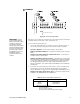
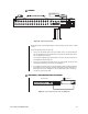
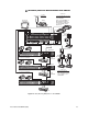
Figure 7. VCR Wiring Example, One VCR (Simplex and Duplex)
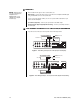
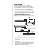
Figure 8. VCR Wiring Example, Two Separate VCRs (Duplex Models Only)
3
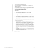
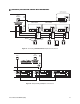
MONITORS
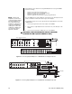
Refer to Table A for the type of video coaxial cable to use.
Main Monitor – Connect the video input of your monitor to the multiplexer’s MAIN output
using standard BNC connector and coaxial cable.
If your color monitor supports SVHS, you can use a special SVHS cable between your
monitor and the multiplexer.
Spot Monitor (Optional) – Connect your spot monitor to the SPOT output.
Auxiliary Monitor (Optional) (Duplex Models Only) – Connect your auxiliary monitor to
the AUX output.
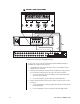
4A
VCR HOOKUP AND HEAD PULSE SWITCHING/PROGRAMMING
If you have a Pelco VCR, proceed to step 4B,
Pelco’s Time-Lapse VCRs
.
NOTE:
Skip this step if
you are connecting your
multiplexer to an
MX4000SVR—or to a
CM6700 SCU (duplex
models only).