
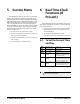
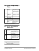
Technical data


10 • XM670K-XM679K I&O Manual 026-1218 Rev 0 19-DEC-2012
8.3.2. Defrost Ending
• When defrost is started via RTC, the maximum de-
frost duration is obtained from the Md parameter
and the defrost end temperature is obtained from the
dtE parameter (and the dtS if two defrost probes are
selected).
•If dPA and dPb are present and d2P=y, the control-
ler stops the defrost procedure when dPA is higher
than the dtE temperature and dPb is higher than the
dtS temperature.
At the end of defrost, the drip time is controlled
through the Fdt parameter.
8.4. Fans
8.4.1. Control With Relay
The fan control mode is selected by means of the
FnC parameter:
• C-n = running with the solenoid valve, OFF during
defrost
• C-y = running with th1e solenoid valve, ON during
defrost
• O-n = continuous mode, OFF during defrost
• O-y = continuous mode, ON during defrost
An additional parameter FSt provides the setting
of temperature, detected by the evaporator probe,
above which the fans are always OFF. This ensures
that air is circulated only if the temperature is lower
than set in FSt.
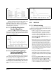
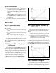
8.4.2. Control With Analog Output
(If Present)
The modulating output (trA=rEG) works in a pro-
portional manner (excluding the first AMt seconds
where the fans speed is the maximum). The regulation
setpoint is relative to the regulation setpoint and is in-
dicated by the parameter ASr, the proportional band
is always located above the SET+ASr value and its
value is PbA. The fans are at minimum speed (AMi)
when the temperature read by the fan probe is
SET+ASr and the fans are at maximum speed
(AMA) when the temperature is SET+ASr+PbA.
8.5. Anti-Sweat Heaters (If
Present)
This control is performed when trA=AC. In this
case, there are two ways to control the anti-sweat
heaters:
• Without real dewpoint information: in this case, the
default value for dewpoint is used (SdP parameter).
• Dewpoint received from the XWEB5000 system:
the SdP parameter is overwritten when the valid val-
ue for dewpoint is received from XWEB.
The P4 probe is used to perform the regulation and
it should be placed on the showcase glass. In case of
P4 error or if P4 is absent, the output is at AMA value
for the AMt time then the output is at 0 value for the
time 255-AMt time performing a simple PWM mod-
ulation.
8.6. Auxiliary Output
The auxiliary output is switched ON and OFF by
means of the corresponding digital input or by press-
ing and releasing the DOWN key.
Figure 8-4 - Control with Analog Output
Figure 8-5 - Anti-Sweat Heaters