
Technical data


16 • XM670K-XM679K I&O Manual 026-1218 Rev 0 19-DEC-2012
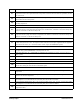
ALd
Temperature alarm delay: (0 to 255 min) The time interval between the detection of an alarm condition and
the corresponding alarm signaling.
dLU
High temperature alarm (defrost probe): (ALC= rE, 0 to 50°C or 90°F / ALC= Ab, ALL to 150°C or 302°F)
When this temperature is reached and after the ddA delay time, the HAd alarm is enabled.
dLL
Low temperature alarm (defrost probe): (ALC = rE, 0 to 50 °C or 90°F / ALC = Ab, - 55°C or - 67°F to ALU)
when this temperature is reached and after the ALd delay time, the LAd alarm is enabled.
dAH
Differential for temperature alarm (defrost probe): (0.1°C to 25.5°C / 1°F to 45°F) Intervention differential
for recovery of temperature alarm.
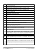
ddA
Temperature alarm delay (defrost probe): (0 to 255 min) time interval between the detection of an alarm
condition and the corresponding alarm signaling.
FLU
High temperature alarm (defrost probe): (ALC= rE, 0 to 50°C or 90°F / ALC= Ab, ALL to 150°C or 302°F)
when this temperature is reached and after the FAd delay time the HAF alarm is enabled.
FLL
Low temperature alarm (defrost probe): (ALC = rE, 0 to 50°C or 90°F / ALC = Ab, - 55°C or - 67°F to ALU)
when this temperature is reached and after the FAd delay time, the LAF alarm is enabled.
FAH
Differential for temperature alarm (defrost probe): (0.1°C to 25.5°C / 1°F to 45°F) Intervention differential
for recovery of temperature alarm.
FAd
Temperature alarm delay (defrost probe): (0 to 255 min) time interval between the detection of an alarm
condition and the corresponding alarm signaling.
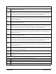
dAO
Delay of temperature alarm at start-up: (0min to 23h 50min) The time interval between the detection of the
temperature alarm condition after the device power on and the alarm signaling.
EdA
Alarm delay at the end of defrost: (0 to 255 min) Time interval between the detection of the temperature alarm
condition at the end of defrost and the alarm signaling.
dot Temperature alarm exclusion after door open:
Sti
Stop regulation interval (Only XM679K): (0.0 to 24.0 hours: tens of minutes) After regulating continuously
for Sti time, the valve closes for Std time to prevent ice from forming.
Std
Stop duration (Only XM679K): (0 to 60 min.) Defines the stop regulation time after Sti. During this stop
display shows StP message.
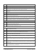
OA6
Sixth relay configuration (CPr-dEF-Fan-ALr-LiG-AUS-db-OnF): CPr= relay works as a compressor or
solenoid valve relay; dEF= relay works as defrost relay; Fan= relay works as a Fan relay; ALr= activation
with alarm conditions; LiG= light activation; AUS= auxiliary relay, it can be switched ON/OFF also by key;
db= dead band regulation (not compatible with CrE = y); OnF= ON/OFF functioning.
OPTIONAL OUTPUT (AnOUT) If Present
OA7
Modulating output configuration (if CoM=0A7): (CPr - dEF - FAn - ALr - LiG - AUS - db) it selects the
functioning of the modulating output in case of CoM=OA7: CPr= compressor; dEF= defrost; FAn= Fan; Alr=
Alarm; LiG= Light; AUS= auxiliary; db= neutral zone (not available with CrE=Y)
CoM
Type of functioning modulating output:
For models with PWM / O.C. output -> PM5= PWM 50Hz; PM6= PWM 60Hz; OA7= two state, it can be
used as an open collector output
For models with 4 to 20mA / 0 to 10V output -> Cur= 4 to 20mA current output; tEn= 0 to 10V voltage output
AOP Alarm relay polarity: cL= normally closed; oP= normally opened
iAU
Auxiliary output is unrelated to ON/OFF device status: n= if the device is switched off also the auxiliary
output is switched off; Y= the auxiliary output state is unrelated to the ON/OFF device status
Table 9-1 - XM670K to XM679K Parameters List