
Technical data


22 • XM670K-XM679K I&O Manual 026-1218 Rev 0 19-DEC-2012
11 Installation and
Mounting
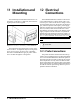
The CX660 keyboard should be mounted on a ver-
tical panel, in a 29 mm x 71 mm hole, and secured us-
ing the special bracket supplied.
The temperature range allowed for correct opera-
tion is 0 to 60°C. Avoid places subject to strong vibra-
tions, corrosive gases, excessive dirt, or humidity.
The same recommendations apply to probes. Allow
air to circulate through the cooling holes.
12 Electrical
Connections
The XM670K/XM679K controllers come with a
screw terminal block to connect cables with a cross
section up to 1.6 mm
2
for all the low voltage connec-
tions: the RS485, the LAN, the probes, the digital in-
puts, and the keyboard. Other inputs, power supply,
and relay connections are provided with a Faston con-
nection (5.0 mm). Heat-resistant cables have to be
used. Before connecting cables verify that the power
supply complies with the controller’s requirements.
Separate the probe cables from the power supply ca-
bles, from the outputs and the power connections. Do
not exceed the maximum current allowed on each re-
lay; in case of heavier loads, use a suitable external
relay.
12.1.Probe Connections
The probes should be mounted with the bulb up-
wards to prevent damages due to casual liquid infiltra-
tion. It is recommended that the thermostat probe be
placed away from air streams to measure the average
room temperature correctly. Place the defrost termi-
nation probe among the evaporator fans in the coldest
place, (where most ice is formed) and far from heaters
or from the warmest place during defrost to prevent
premature defrost termination.
Figure 11-1 - Installation and Mounting of XM670K/XM679K
NOTE: Maximum current allowed for all the
load is 16A.