
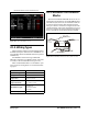
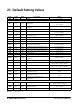
Technical data


42 • XM670K-XM679K I&O Manual 026-1218 Rev 0 19-DEC-2012
dPE 100 Pr1
Virtual probe percentage (defrost
temperature)
0 to 100 (100=dPA, 0=dPb)
tdF EL Pr1 Defrost type EL(0) - in(0)
EdF in Pr1 Defrost mode: Clock or interval rtc(0) - in(1)
Srt 150 Pr1 Heater setpoint during defrost
[-55.0°C to 150°C]
[-67°F to 302°F]
Hyr 2.0 Pr1 Differential for heater
[0.1°C to 25.5°C]
[1°F to 45°F]
tod 255 Pr1 Time out for heater 0 to 255 (min.)
dtP 0.1 Pr1
Minimum temperature difference to start
defrost
[0.1°C to 50.0°C]
[1°F to 90°F]
ddP 60 Pr1 Delay before starting defrost 0 to 60 (min.)
d2P n Pr1 Defrost with two probes n(0) – Y(1)
dtE 8.0 Pr1
Defrost termination temperature (Probe
A)
[-55.0°C to 50.0°C]
[-67°F to 122°F]
dtS 8.0 Pr1
Defrost termination temperature (Probe
B)
[-55.0°C to 50.0°C]
[-67°F to 122°F]
idF 6 Pr1 Interval between defrosts 0 to 120 (hours)
MdF 30 Pr1 Defrost Maximum duration 0 to 255 (min.)
dSd 0 Pr1 Start defrost delay 0 to 255 (min.)
dFd it Pr1 Display during defrost rt(0) - it(1) - SEt(2) - dEF(3)
dAd 30 Pr1 Defrost display time out 0 to 255 (min.)
Fdt 0 Pr1 Drain down time 0 to 255 (min.)
dPo n Pr1 Defrost at start-up n(0) – Y(1)
dAF 0.0 Pr1 Defrost delay after continuous cycle 0 to 24.0(144)(hours.10min)
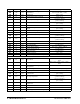
FAN
FPA P2 Pr1 Fan probe A
nP(0) - P1(1) - P2(2) - P3(3) - P4(4) -
P5(5)
FPb nP Pr1 Fan probe B
nP(0) - P1(1) - P2(2) - P3(3) - P4(4) -
P5(5)
FPE 100 Pr1
Virtual probe percentage (fan
management)
0 to 100 (100=FPA, 0=FPb)
FnC O-n Pr1 Fan operating mode C-n(0) - O-n(1) - C-y(2) - O-y(3)
Fnd 10 Pr1 Fan delay after defrost 0 to 255 (min.)
FCt 10 Pr1
Temperature differential to avoid short
cycles of fans
[0.0°C to 50.0°C]
[0°F to 90°F]
FSt 2.0 Pr1 Fan stop temperature
[-55.0°C to 50.0°C]
[-67°F to 122°F]
FHy 1.0 Pr1 Fan stop differential
[0.1°C to 25.5°C]
[1°F to 45°F]
Fod 0Pr1
Fan activation time after defrost (without
compressor)
0 to 255 (min.)
Fon
0 Pr1 Fan ON time 0to15 (min.)
FoF 0 Pr1 Fan OFF time 0to15 (min.)
trA UAL Pr2 Kind of regulation for modulating output UAL(0) - rEG(1) - AC(2)
Label Value Menu Description Range
Table 23-1 - Default Setting Values