
User manual
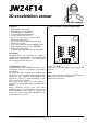

Code Mercenaries
1
JJ
JJ
WW
WW
22
22
44
44
FF
FF
11
11
44
44
1. Features
• USB interface (low speed)
• Full USB V1.1/2.0 compliance
• Full USB HID 1.1 compliance
• 3 axis acceleration measurement
• 14 bit resolution for each axis
• ±1g, ±1.5g, ±2g, ±3g, ±4g, ±8g, or ±16g
software selectable range
• Data can be read via joystick input or direct
• 8 buttons/aux inputs
• Uses a state of the art compact MEMS sensor
• Sensor settings can be stored in EEPROM
• Single +5V power supply
• Available as module, kit, and water proof unit
1.1 Variants
JoyWarrior24F14 are available as either a
completely assembled module, a kit containing the
module, cable and enclosure, or as a water proof
unit in a rugged plastic enclosure.
2. Functional overview
JoyWarrior24F14 uses a MEMS solid state 3 axis
acceleration sensor for acceleration or inclination
measurement.
By default the data is reported as joystick data
which allows to use JoyWarrior24F14 with existing
applications and simplifies implementation for
applications where no detailed handling of the
sensor parameters is required.
Full access to the sensor data and settings is
possible via a generic HID interface (similar to IO-
Warrior).
Range, bandwith, trigger levels, and other
parameters can be set permanently in the sensors
internal EEPROM. This allows to program the
sensor for a specific application and then use the
joystick data for easy access.
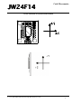
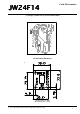
3.0 Pin description JoyWarrior24F14-MOD
D+, D-, Vcc, GND
Connect to a USB cable with a type A plug on its
other end.
B0..B7
Inputs for the buttons or auxiliary inputs. Connect
contacts closing to ground or pull low.
Internal pull up resistors.
V 1.1.2, November 9th 2015 for Chip Revision V1.0.4.0
3D acceleration sensor