
User manual

Code Mercenaries
22
KK
KK
ee
ee
yy
yy
WW
WW
aa
aa
rr
rr
rr
rr
ii
ii
oo
oo
rr
rr
22
22
44
44
V 1.1.2, December 2nd 2013, for chip revision 1.1.1.4/1.1.1.B and up
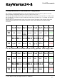
7. DC Characteristics
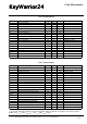
7.1 AC Characteristics
*) A version with fast scanning to better suit rubber dome keyboards is possible for custom versions.
In this case t
scan
= 1ms, t
debounce
= 2x t
scan
and t
scansu
= 10μs
Parameter Min Max Units Remarks
V
cc
I
cc
Operating Voltage
Operating Supply Current
4.35 5.25
20
V
mA
I
sb
I
ol
I
ol
R
up
Suspend mode current
Max sink current on output pins
Sink current on output pins
Pull-up Resistance 8
25
70
μA
mA
2
24
mA
kΩ
Oscillator off
Cummulative across all ports
Vout = 0.4V
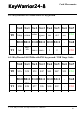
V
ith
V
H
V
oh
Input threshold voltage
Input hysteresis voltage
40%
3%
USB Interface
Static output high 2.8
V
ol
V
di
V
cm
V
se
Static output low
Differential Input sensitivity 0.2
Differential Input common Mode Range
Single Ended Transceiver Threshold
0.8
0.8
60%
10%
V
cc
V
cc
3.6 V
All ports, low to high edge
15kΩ±5% to GND
0.3 V
V
2.5
2.0
V
V
|(D+)-(D-)|
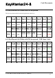
C
in
I
io
R
pu
R
pd
Transceiver capacitance
Hi-Z State Data Line Leakage -10
Bus Pull-up resistance
Bus Pull-down resístance
1.274
14.25
20
10
pF
μA
15.75
15.75
kΩ
kΩ
0V < Vin < 3.3V, Hi-Z State
1.3kΩ±2% to Vreg
15kΩ±5%
Parameter Min Max Units Remarks
clock accuracy
USB Driver Characteristics
-1.5 +1.5 % Derived from USB signal
t
r
t
r
t
f
t
f
Transition rise time
Transition rise time
75
Transition fall time
Transition fall time
75
300
ns
ns
300
ns
ns
CLoad = 200pF
CLoad = 600pF
CLoad = 200pF
CLoad = 600pF
t
rfm
V
crs
t
drate
Rise/Fall Time matching
Output signal crossover voltage
80
1.3
USB Data Timing
Low Speed Data Rate 1.4775
t
djr1
t
djr2
t
deop
t
eopr2
Receiver data jitter tolerance
Receiver data jitter tolerance
-75
-45
Differential to EOP transition skew
EOP width at reeiver
-40
670
125
2.0
%
V
1.5225 MBit/s
75
45
ns
ns
100 ns
ns
To next transition
For paired transitions
Accepts as EOP
t
eopt
t
udj1
t
udj2
Source EOP width
Differential driver jitter
1.25
-95
Differential driver jitter
Keyboard Matrix Scan Timing
-150
t
scan
t
scansu
t
debounce
Scanning interval
Matrix drive to read setup time
4*
typ. 40*
Debounce time
3x t
scan
*
1.50
95
μs
ns
150 ns
To next transition
To paired transition
ms
μs
ms