
Datasheet

Code Mercenaries
3
LL
LL
EE
EE
DD
DD
--
--
WW
WW
aa
aa
rr
rr
rr
rr
ii
ii
oo
oo
rr
rr
00
00
99
99
4. I2C Addressing
LED-Warrior09 uses $20 (7 bit value, needs to be
shifted and extended by R/W bit: 0100 000R)
as the factory default I2C address.
Reassigning a different address is possible via I2C
commands.
4.1 I2C Commands
Commands are implemented via register addresses
that are transmitted as the first byte following the
I2C address byte. Reading from registers is done
by first doing a write transaction transmitting the
I2C address and the register number, then a restart
and a read transaction.
The register number is always reset to zero at the
end of a transaction, so reading without first
writing a register address always returns the
content of the status register.
4.2 Status register
The status register is one byte that contains the bus
status and command status flags:
7 - Bus Status, 0 = Bus OK, 1 = Bus fault
6 - Busy, 0 = ready, 1 = busy
5 - not used
4 - not used
3 - not used
2 - not used
1 - not used
0 - not used
Bus Status = 1 indicates that the bus is not
working, either another device is pulling it
permanently low or the bus is not connected.
Commands to register 1 will be ignored if the bus
is not working.
Busy = 1 indicates that the last command has not
yet been transmitted. Any new command sent to
register 1 will be ignored until the last command
has been transmitted and the busy bit is cleared.
4.3 Command register
The command register has two bytes which
directly contain the DALI command. DALI
commands 0 to 31 and direct arc power control are
supported.
4.3.1 DALI Commands
LW09 accepts the DALI comands 0 to 31 and the
direct arc power control command that directly sets
the power value for the lamp. The commands are
send by writing two bytes to register $01. LW09
will then transmit the command over the DALI bus
and indicate by the busy bit in the status register if
the DALI command has already been shipped.
The first byte contains the address information, the
second holds either the lamp power value or
command code.
4.3.2 DALI Address
The address byte format is used by the Command
register as well as the Config register:
7 - Y, 0 = short address, 1 = group address
6 - A5, Address bit 5
5 - A4, Address bit 4
4 - A3, Address bit 3
3 - A2, Address bit 2
2 - A1, Address bit 1
1 - A0, Address bit 0
0 - S, 0 = DAPC, 1 = Command
The S Bit selects if the second byte is the direct arc
power value (lamp power) or a command code. For
the config register this bit is ignored.
The addressing mode is selected by the Y bit. If
Y= 0 the A0..5 bits contain the 6 bit short address
of the device (0AAA AAAS). Short addresses are
direct addresses for up to 64 individual DALI
devices.
Group addressing can go to any of 16 groups of
devices or to all devices on the DALI bus
(broadcast). If Y = 1 and A4 and A5 are both zero
A0..3 contain the 4 bit group number to which the
command is addressed (100A AAAS).
A broadcast command sets all A bits to 1:
1111 111S This command goes to all devices on
the connected DALI bus.
Address values 1010 0000 through 1111 1101 are
invalid and will result in the command being
ignored.
In case of a direct arc power control command the
second byte directly sets the lamp power, where 0
is off and 254 is maximum, 255 is a mask value
that stops any fading at the current power level.
The functions of the other DALI commands are
described in the following section.
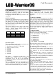
Register
$00
$01
R/W Function
R
W
Status
Command
Data
1 Byte
2 Bytes
$08
$FE
R/W
W
Config
Set Addr
4 Bytes
2 Bytes
V1.0.0 April 8th 2015