
User's Manual

OCT/02/2002
CA-120
1
MODEL CA-120
REMOTE CONTROL AUTO ALARM SYSTEM
INSTALLATION & OPERATION INSTRUCTIONS
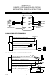
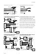
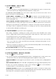
WIRING DIAGRAM
H1
: Main 6 Pin White harness
H7
: 6 Pin White Mini Connector
Black Antenna Wire
LED Indicator
Valet Switch
H6 4 Pin
Orange
H3 2 Pin
Blue
H2 2 Pin
White
H5 Black
Wire
Dual Zone
Shock
Sensor
H4
: 6 Pin Door Lock/Unlock
Wire harness
H1 6 Pin
White
H4 6 Pin
White
H7 6 Pin
White
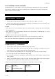
H1: MAIN 6 PIN WHITE WIRE HARNESS:
6. Red W ire: +12V To Constant Batter
y
Source
5. Brown W ire: Positive output To
4. Black Wire: Ground to Vehicle FRAME
1. W hite W ire: Turn Indicator Relay Output
2. Red / White Wire: Turn Indicator Relay Power input
Siren Or Horn (Programmable)
3. W hite W ire: Turn Indicator Relay Output
Turn Indicator
15A Fuse
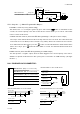
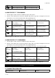
H7: 6 PIN WHITE MINI CONNECTOR WIRE HARNESS:
6. Gray Wire: (-) 200mA Programmable Output
2. Blue Wire: Zone 2 / Instant Trigger Ground Input
1. Violet Wire:
Zone 3
/ Positive Door Pin Switch Input
4. Yellow Wire: Zone 5 / To I
g
nition Switched + 12V
5. Orange Wire: 200mA Grounded when armed
3. Green Wire:
Zone 3
/ Negative Door Pin Switch Input
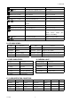
85
86
30
87a
Cut
To start solenoid
From ignition switch
Red wire
White wire
Orange
wire
Channel 3 / 2 Step Door Unlock / Pager Output.
12V
12V
Yellow wire