
Installation Manual

10
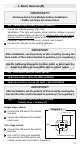
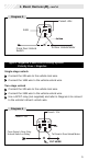
20/B Positive/Negative Door Input (20 AWG) (GREEN/VIOLET)
Connect the 20/B wire to the vehicle pin switch or courtesy light
circuit.
Verification
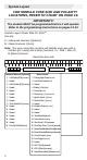
- Refer to Vehicle Wire Color and Location Chart for circuit
type and location, or verify the vehicle wire using the following guideline:
•
Positive Systems
- Target wire registers voltage
when any door is opened.
•
Negative Systems
- Target wire registers ground
when any door is opened.
Important!
After installation, select the polarity of this circuit in programming
Option Bank 2/Feature 1 (factory default = negative), page 13.
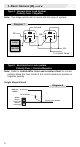
NOTE:
FOR POSITIVE SYSTEMS, TEMPORARILY CONNECT THE 20/B WIRE TO GROUND
IN ORDER TO ACCESS THE PROGRAMMING MODE. REFER TO PAGE 11.
CHANGE OPTION BANK 2/FEATURE 1 TO POSITIVE POLARITY (PAGE 13).
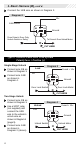
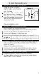
22/B LED2 (20 AWG+)
23/B LED1 (20 AWG-)
Locate a visible section of the dash with 1" clearance behind
the location.
Drill a
9
/
32
" hole and snap the Status Indicator into place.
Connect the Status Indicator Red Wire to the 22/B LED2 wire.
Connect the Status Indicator Black Wire to the 23/B LED1 wire.
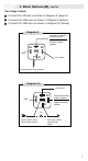
Tip: To change the Red LED to a Green LED:
Connect the status indicator Black wire to the 22/B LED2 wire.
Connect the status indicator Red wire to the 23/B LED1 wire.
1. Basic Harness (B),
cont’d.
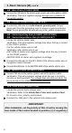
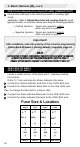
Fuse Size & Location
Trunk
Output
Dome
Light
Parking
Lights
Door
Locks
|| || ||
||
|| || ||
||
|| || ||
||
|| || ||
||
|| || ||
||
Heater 1 Heater 2 Ignition 1/2
Main Power
15A 15A 15A
25A
+ + +
+
_ _ _
_
25A 25A 25A
5A