
Installation Manual

3
1. Basic Harness (B)
IMPORTANT!!!
• Remove fuses from Module before installation.
• Solder and tape all connections.
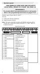
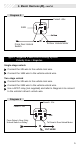
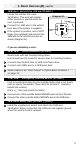
1/B Parking Light Output (20 AWG) (WHITE)
Locate the vehicle parking light wire.
Verification:
This wire will register either positive voltage or ground
when the parking lights are turned on. Voltage does not vary when
dimmer switch is adjusted. Refer to the Vehicle Wire Color and
Location Chart for the wire color, polarity, and location.
Connect the 1/B wire to the parking light wire.
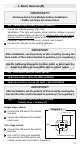
IMPORTANT!
After installation, set the polarity of this circuit by moving the
fuse inside of the control module to positive (+) or negative(-).
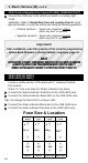
Use the following diagrams for door locks or purchase the
Advanced Harness and utilize the on-board relays.
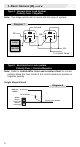
2/B Lock Motor Wire (20 AWG) (BLUE)
14/B Unlock Motor Wire (20 AWG) (GREEN)
24/B Second Door Unlock (20 AWG -) (BLUE/GREEN)
IMPORTANT!
After installation, set the polarity of this circuit by moving the
fuse inside of the control module to positive (+) or negative(-).
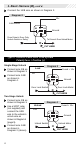
Type 1: Positive 3-wire door lock system -
Polarity Fuse = Positive (+)
Single-stage unlock
Connect the 2/B wire to the vehicle
lock wire.
Connect the 14/B wire to the vehicle
unlock wire.
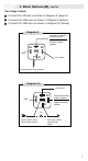
Two-stage unlock
Connect the 2/B wire to the vehicle
lock wire.
Use a SPDT relay (not supplied)
and connect the 24/B wire to the
vehicle unlock wire as shown in Diagram 1.
86
87
85
30
87a
Fused + 12v
To vehicle unlock wire
Diagram 1
24/B