
Installation Manual

4
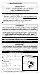
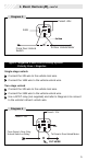
Connect the 14/B wire as shown in Diagram 2.
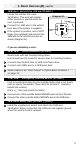
Type 2: Positive 5-Wire Door Lock System
Polarity fuse = Positive (+)
Single-Stage Unlock
Connect wire 2/B as
shown in Diagram 3.
Connect wire 14/B
as shown in
Diagram 4.
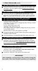
Two-Stage Unlock
Connect wire 2/B as
shown in Diagram 3.
Use a SPDT relay
(not supplied) and
connect the 24/B
wire to the vehicle’s
unlock wire as
shown in Diagram 5
(page 5).
Connect wire 14/B
as shown in
Diagram 2 (above).
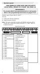
1. Basic Harness (B),
cont’d.
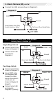
X
86
87
85
30
87a
12v
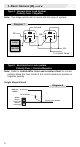
Diagram 2
14B Unlock
Ground
From Driver’s Door Only
Unlock Switch or Relay To Driver’s Door Unlock Motor
CUT HERE
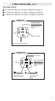
X
86
87
85
30
87a
CUT HERE
14B
Ground
Unlock MotorUnlock Switch
Unlock
Diagram 4
Fused + 12v
X
86
87
85
30
87a
Diagram 3
CUT HERE
2B
Ground
Door Lock Switch Door Lock Motor
Lock
Fused + 12v