
Installation Manual

8
1. Basic Harness (B),
cont’d.
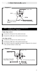
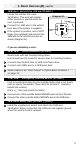
4/B Main Power (14 AWG) (RED)
Connect the 4/B wire to the vehicle main power wire at the ignition switch.
Verification:
This wire registers voltage through every position of
the ignition switch.
5/B Chassis Ground (14 AWG) (BLACK)
Connect the 5/B wire to a solid chassis ground point. Scrape
away paint from the grounding point to ensure a good connection.
Note: Do not ground the 5B wire with any other vehicle components.
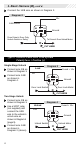
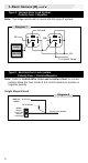
6/B Starter Input Key Side (14 AWG) (VIOLET/RED)
8/B Starter Output Motor Side (14 AWG)(VIOLET)
Locate the vehicle starter wire.
Verification:
This wire registers voltage
only
when the key is turned
to the START position.
Cut the vehicle starter wire in half.
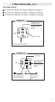
Verification after starter wire is cut:
•KEY SIDE of starter wire registers voltage when the key is turned
to the START position.
•MOTOR SIDE of starter wire registers no voltage.
Connect the 6/B wire to the KEY SIDE of the vehicle starter wire at
the ignition switch harness.
Connect the 8/B wire to the MOTOR SIDE of the vehicle starter wire.
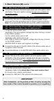
7/B Ignition 1 Input (14 AWG+) (PINK)
Connect 7/B wire to the vehicle ignition wire at the ignition switch.
Verification:
This wire registers voltage when the key is turned to
the ON (or RUN) position. The voltage does not drop out when the
key is turned to the START (or CRANK) position.
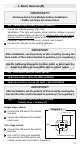
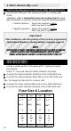
13/B Trunk Release Output (TAN)
Locate the vehicle trunk release wire.
Verification:
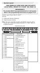
Refer to the Vehicle Wire Color and Location Chart
for the wire color, polarity, and location.
Connect the 13/B wire to the vehicle trunk release wire.
IMPORTANT!
After installation, set the polarity of this circuit by moving the
fuse inside of the control module to positive (+) or negative(-).