COEF srl. Via Albinatico, 80-82 51019 Ponte Buggianese (PT) ITALY www.coef.it / www.coef.net Sirio 150 / 150DV Graphic by PC CAD & VIDEO info@coef.
INTRODUCTION Thank you for using the Sirio 150 / 150DV ! The Sirio 150 / 150DV projects, thanks to an extremely efficient optic system (international patent n. WO99/40361), a powerful light beam which can create numberless color shades. Its performances, in terms of luminousity and lighted surfaces, can reach incredible levels. The Sirio 150 / 150DV comes in two versions: • Cod. 02B010 Sirio 150 for Mastercolour 150W (CDM-T 150W/942 - CDM-SA/T 150W/942). • Cod.
DANGER SIGNAL: Generic dager signal and electric shock danger signal. GENERAL WARRANTY CONDITIONS • • • • • • • • The guarantee is valid for a period of 12 months from the date of purchase of the equipment. The guarantee is not valid in case a wrong voltage or frequency is selected. The parts which are proved to have manufacturing defects are also covered by the guarantee.
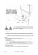
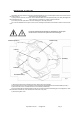
DMX IN - DMX OUT fig.1 POWER INPUT The equipment must be earthed. If this rule is not followed, the warranty will be void. IP 66 grade: to ensure the declared IP grade choose the correct size of the cables (from 3 to 6.5mm). All the gaskets and the glass must be keeped in full working order. BEFORE USING Read all cautions and warnings to page 1 prior to install this equipment.
INSTALLATION OF THE LAMP d) Replace the lamp when the lamp life is exhausted (6000 hours) to avoid bad peformances of the fixture or that the optic system is damaged by the lamp explosion. e) The protection screens, the lenses, or the ultraviolet filters must be replaced if they are visibly damaged and their effectiveness has been reduced, for example, by cracks or deep scratches. f) The lamp must be replaced if it has been damaged or thermally deformed.
CONNECTION TO THE MAINS POWER AND TO THE DMX SIGNAL / REPLACING FUSES To connect the Sirio 150 / 150DV to the mains power, remove the cover located behind the fixture, and connect the cable to the electronic board as shown in pict. 3. The connection to the DMX signal to the Sirio 150 / 150DV must be made by using standard DMX cables as shown in pict. 3/a HIGH VOLTAGE! Always disconnect the mains supply before opening the connections area.
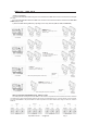
SIRIO 150 / 150DV SETUP • DMX 512 CONTROL 1) Connect the DMX data cable coming from the controller to the DMX-IN connector on the electronic board (see pict. 3/a). 2) Connect the DMX data cable to the DMX-OUT connector on the electronic board to control the next Sirio 150 / 150DV (see pict. 3/a). 3) Select the DMX starting address by operating on the rotary switches (UNITS, TENS, HUNDREDS).
• AUTO - MODE CONTROL 1) Set n° 6 on the HUNDREDS rotary switch (MASTER). 2) Choose the games by operating on the UNITS and TENS rotary switches. Available games: from n° 1 to n° 15 (see appendix “B”). Game n° 11 is the one which enables all the colors. • SYNCHRO - MODE CONTROL (pict. below) 1) Interconnect all the Sirio 150 / 150DV (max 32) by using the DMX standard cables. 2) Set the first Sirio 150 / 150DV as MASTER by setting n° 6 on the HUNDREDS rotary switch.
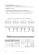
APPENDICE “B” Complet list of available games http://www.coef.net - info@coef.it Pag.