
Operating instructions


http://www.coef.net - info@coef.it Pag. 7
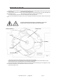
SIRIO 150 / 150DV SETUP
• DMX 512 CONTROL
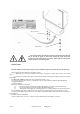
1) Connect the DMX data cable coming from the controller to the DMX-IN connector on the electronic board (see
pict. 3/a).
2) Connect the DMX data cable to the DMX-OUT connector on the electronic board to control the next Sirio 150 /
150DV (see pict. 3/a).
3) Select the DMX starting address by operating on the rotary switches (UNITS, TENS, HUNDREDS).
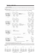
EXAMPLE 2:
2 or more DMX 512 Output
Connection controller-sopt with 2 or
more DMX512 Output
EXAMPLE 1:
1 DMX 512 OUTPUT
Connection controller-spot with 1
DMX512 Output
EXAMPLE 3:
Connection controller-spot to 1
DMX512 Output over 150mts long
DMX Signal
Amplifer
LINE> 150mt. (With microphonics or audio cable)
DMX line
terminator
Consolle DMX
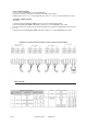
DMX 512 CHANNELS ASSIGNEMENT IN THE SIRIO150 / 150DV
The rotating switches to assign the channels DMX 512 are located on the printed circuit of the electronics which is inside the
connections area. There are three rotating switches, and each one is numbered from 0 to 9: one for the UNITS, one for the TENS,
one for the HUNDREDS. In the picture below it is shown the position of the three switches when using four Sirio 150 / 150DV in
DMX 512.
Spot N.1
Spot N.2
Spot N.3
Spot N.4
Channels 1-6
Channels 7-12
Channels 19-24
DMX line
terminator
DMX line
terminator
DMX line
terminator
Consolle DMX
Consolle DMX
DMX Signal
Amplifer
DMX line
terminator
LINE> 150mt. (With microphonics or audio cable)
EXAMPLE 4:
Connection controller-spot to 1
DMX512 Output over 150mts long
Consolle DMX
Channels 13-18