COEF srl. Via Albinatico, 80-82 51019 Ponte Buggianese (PT) ITALY www.coef.it / www.coef.net Realized by PC CAD & VIDEO Mp 700 zOOM info@coef.
Declaration of CE conformity We Manufacturer COEF srl. Via Albinatico, 80-82 / 51019 Ponte Buggianese (Pistoia) ITALY Declare that the product MP700 Zoom is in conformity with 89/336 EEC-EMC directive and with the actual required safety standars in accordance with LVD 73/23 EEC Ponte Buggianese, 10 October 2001 ATTENTION: carefully read the directions of this manual.
This manual has been organized in order support the user, the installer or the maintenance operator of the described unit with those necessary informations for a correct use of the installation and working procedures of the same unit.The various procedures will be just signalled by indicators (when necessary) evidencing the operation dangers and the necessity of technical support.
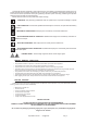
1.0 DIMENSIONS & POSITIONING It is possible to set up the MP700 Zoom in any position. 2.0 TECHNICAL NOTES MP700 Zoom DV with Magnetic Ballast MP700 Zoom DVP with Electronic Ballast • • • • • • • • • • • • • • • • • • • • • • • • • • • • • • Pag. 4 Code: 02E010 Code: 02E011 Lamp: MSR 700 SA 700W 54.
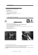
3.0 INSTALLATION The constructor is not be considered responsible in case of: • • • • • • • • • Improper use fo the unit or use by not trained staff Use in contrast with the directions on work safety Wrong installation Defective power supply Serious lacks in the necessary maintenance Unauthorized modifications and interventions Use of spare parts that are not original or not specific for the unit Total or partial inobservance of instructions Unusual events 3.
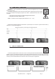
3.2 OPERATING VOLTAGE WARNING : unplug the fixture from the power supply before operating . The operation must be performed only by highly specialized staff. WARNING : The wrong selections of the operating tension and/or frequency compromise the good operation of the fixture and will immediately invalid the COEF warranty. 3.3 Settings for magnetic ballast Cod. 02E010 The fixture can work at the following tensions : 230 V~50 / 60 Hz and 208 V~ 60 Hz (optional).
4.0 - POWER SUPPLY CONNECTIONS WARNING: In order to guarantee the utmost safety, connect the apparatus only to a properly earthed mains system. The projector is designed to work at the tension and frequency indicated by the electrical data label on the rear. Before connecting the projector to the mains, a qualified electrician must check its conformity. • The projector must be protect by an adeguated magneto-thermal switch . • Don't power the unit with a dimmer circuit.
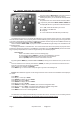
5.0 SPECIAL FUNCTIONS AND PROJECTOR ASSIGNMENT On the front panel of MP700 Zoom you'll find a section for the additional functions and for setting the projector. Following the picture, you can see all the offered possibilities in detail. All operations are to be carried out with the E, F, G, H buttons, respectively indicated as MENU, ENTER, DOWN and UP. The display D will inform you about the selected functions. The 3 A, B, and C leds will allow you to know: A = reception of the DMX line. B = lamp ON.
6.
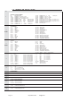
7.0 CHANNELS AND DIGITAL VALUES CH 1 2 MODE1 2 MODE2 SHUTTER / STROBE / DIMMER 0-5 SHUTTER closed 6-100 DIMMER from channel 14 value 101-110 DIMMER 0 > 100% Automatic 6 sec. 111-120 DIMMER 100% > 0 Automatic 6 sec.
CH 12 EFFECTS (Frost - Prism) 0-5 Neutral 6 - 20 Automatic FROST from 0 to 100% (velocity adjustment) 21 - 40 Automatic FROST from 100% to 0 (velocity adjustment) 41 - 60 Frost 61 - 80 Prism 3 faceted 81 - 170 CW PRISM rotation with velocity adjustment 171 - 255 CWW PRISM rotation with velocity adjustment 13 IRIS 0-5 6 - 130 131 - 150 151 - 170 171 - 190 191 - 210 211 - 230 321 - 250 251 - 255 Open / Neutral IRIS with manual regolation (100% - 0) IRIS closed IRIS 0 - 100% IRIS 100% - 0 IRIS 0-100%-0 sl
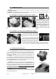
8.0 LAMP ADJUSTMENT • Don’t look directly the beam trough the lens. • The lamp is pre-regulated by the factory. Only fine-adjustment. Don’t move the screws ”C” up to upper or lower extremities. Lamp adjustment is necessary to obtain a uniform and powerful light beam. Switch on the projector and set the channels without gobo and colors. Adjust the three screws C until you reach the ideal condition between power and homogeneity. 9.
10.0 ORDINARY MAINTENANCE Ordinary maintenance on the projectors MP 700 Zoom is necessary to maintain the perfect efficiency of the unit and to avoid defects like the low luminosity of the light beam or the elevated overheating of the equipment. In the figures you can see those components that can easily accumulate dust and grease. Clean them using a soft cloth and common glass-cleaners. 10.
You must particularly take care of the sensors which are really fundamental in the unit working. The sensors are absolutely necessary when a general reset of the projector is needed. If this function is not correctly executed, it will totally compromise the regular working of the projector, at least for the group referred to the sensor itself. The sensors of the encoders concerning the PAN and TILT movements are located in the base and in the arm of the MP700 Zoom respectively.
10.2 ELETTRONIC MAINTENANCE WARNING: switch off the projector before operating This section is dedicated in detail to the electronic connections between the card and the mechanical components, assembled in the projector. These informations will be absolutely necessary when the mechanical unit has to be removed from the projector for maintenance and/or repair.
11.0 TROUBLESHOOTING PROBLEM The projector doesn’t swich on CAUSE ACTION - The power supply is not present Check if the luminous indicator is lighted or not. - The lamp is not working Replace the lamp. - The thermal switch is active Just to wait for little of time. The projector swiches on but - Wrong DMX configuration doesn’t answer to commands Defecting projection Make sure that the projector is correctly configurated. - Defective cables Replace or repair the DMX cable.