Smart Gate Installation Guide FCC ID : TLDSPS-TS THIS DEVICE COMPLIES WITH PART 15 OF THE FCC RULES. OPERATION IS SUBJECT TO THE FOLLOWING TWO CONDITIONS. (1) THIS DEVICE MAY NOT CAUSE HARMFUL INTERFERENCE AND (2) THIS DEVICE MUST ACCEPT ANY INTERFERENCE RECEIVED , INCLUDING INTERFERENCE THAT MAY CAUSE UNDESIRED OPERATION.
FCC Compliance and Advisory Statement This device complies with Part 15 of the FCC rules. Operation is subject to the following two conditions: 1) this device may not cause harmful interference, and 2) this device must accept any interference received, including interference that may cause undesired operation. This equipment has been tested and found to comply with the limits for a Class B digital device, according to Part 15 of the FCC rules.
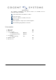
Tabl e of Cont ent 1. 2. 3. 4. 5.
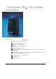
1, Product Description Plastic Housing Standard Features Standard features of Smart Gate are: 500 DPI silicon fingerprint sensor Magnetic stripe card reader Standalone or networked operation Configurable security levels Remote configuration through network connection or local configuration through RS232 10/100 Base-T Ethernet connections for communication with a central database and/or administrative software 1:1 authentication or 1:N identification Wiegand output Relay drive output 209 Fair Oaks Avenue
Optional Features The following configurations and optional features are available from the Smart Gate range of terminals: Central administration and database software Contact (ISO 7816) Contact less (MiFare™ 14443A) smart card Match-On-Card Memory upgrade for storage of up to 6,000+ fingerprints Server matching using Ethernet connection 2, Accessories: 1. DB15 Cable 2. USB Cable 3. Screws, Security For Plastic Housing For Aluminum Housing 4. Screw Driver For Plastic Housing 5. Installation Guide 6.
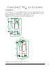
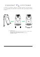
3, Installation 137. 00 3. 1 Fol l ow Fi g. 1 t o dr i l l mount i ng hol e on t he wal l whi ch t he devi ce wi l l i nst al l ( no need t he mount i ng hol e i f mount i ng on t he st andar d el ect r i cal box) . Open t he back panel f r om t he devi ce ( f ol l ow i nst r uct i on 3. 3) . Anot her opt i on can be used i n t he pl ast i c housi ng( Fi g. 2) . 80. 00 137. 00 Fi g. 1 80. 00 Fi g. 2 3. 2 Mount t he back panel on t he wal l out l et f i rst . 209 Fair Oaks Avenue South Pasadena, CA 9
3. 3 Pl ug al l t he necessar y connect or s ( l i ke DB15, Net cabl e) on t he mai n devi ce f i r st , t hen mount t hi s mai n devi ce on t he back panel by f ol l owi ng t he bel ow pr ocedur es. Tips for Plastic Housing: 1. Plug the main device all the way in from above the back panel 5 cm height, then push down make sure well contact with back panel and lock. 2. Lock the Device by using the security screws provided from factory. 3. Assembly covered plate.
4. Smart-Gate User Manual 1 Preparation: 1.1 Make sure the S2 switch is on “Card Management Mode” (Default setting). 1.2 Connect the Smart Gate with Category 5 network cable to network switch. Please use POE switch if try to use POE features. 1.3 Connect the Smart Gate with the COM1 of PC by using special serial cable (come with Smart Gate) 1.4 Connect the power (12V DC power supply to pin 13, 11 of DB15 socket if not using POE). 2 How to use: 2.1 Network Setting: 2.1.
yellow LED is on and green LED flash. f, the device will be in delete work mode if present Admin card in the front of the device again, and keeping enroll the new card if present another blank card. 2.2.3 Matching fingerprint: in verify work mode match the fingerprint with minutia in the card, the yellow LED of device will flash and the device request the card.
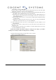
b, Assign IP address for the device(Default setting: 172.60.5.103), click “Save” c, Change Gate mode to “verify” and click “Report” (Picture 3) 图3 d, Read card and matching with captured fingerprint image, Granted if the fingerprint had been enrolled into the card or denied if the fingerprint is not the one enrolled into the card. All the access log will be send to data bank through network. 2.2.
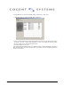
Appendix A: Hyper Terminal (admin functions): 1, Open: \Start\AllPrograms\Accessories\Communications\HyperTerminal. (see picture 4) Picture 4 2, Typing in any “Name” in “Connection Description” windows (for example: test), then click “OK” (picture 5). Picture 5 Picture 6 3, Choosing ”COM1” in “Connect using” of “Connect To” windows (make sure the serial cable is connect to the same port) (picture 6). 4, In “Port Setting” windows, choosing “9600” for Bits per second and “Xon / Xoff” for “Flow control”.
Picture 7 Picture 8 5, Then click “OK” to complete the setting, hit the “Enter” key again and should display picture 8.
Appendix B: Jumper S2 setting I. Card Mode: 1. Admin mode: Default Setting (Enroll, Verify & Delete) S2 setting 2. Verify mode only: S2 setting II. Fingerprint only (No card needed) 1. Enroll Mode: 2.
5. Specification Smart-Gate Technical Specifications: Fingerprint sensor: Silicon sensor (500DPI) Enrolment method: Single finger ,multiple enrollments Extraction &Identification time: ~ 1.5 seconds FRR: FRR 0.1%-0.001% FAR: FAR 0.01%-0.0001% Allowable finger rotation: +/- 15 Template Size: 784bytes I/O interface: RS232, RS485 Baud Rate: 9600-115kbps programmable Ethernet: 10/100 w/P.O.E. Fully 802.
POE The Ext Board Supplies the main power to the Smart Gate device . The main power comes from POE or DB15 socket. In order to use the nonstandard and standard POE device ,Jumper J5,J6 are used. Details see below. Figure 1.
Standard POE Device Power Supply If the POE device that supply power to the Smart Gate device meets the standard POE specification, that is to say, the voltage of POE device is 48V, The pin1 and pin2 of the jumper 5 (JP5) and jumper 6 (JP6) are connected together .Illustrated as Figure 1.1 . In this application, the input voltage range of the Smart Gate device that the POE device supply is 40V~60V. Figure 1.
NonStandard POE Device Power Supply If the POE device that supply power to the Smart Gate device does not meets the standard POE specification, that is to say, the voltage of the POE device is below 48V, The pin2 and pin3 of the jumper 5 (J5) and jumper 6 (J6) are connected together . Illustrated as Figure 1.2 . In this application, the input voltage range of the Smart Gate device that the POE device supply is 12V~40V.
DB15 Socket The User can use DB15 socket to get various output signals of Cogent’s Smart Gate device . In the meantime, the user can input some signals to Cogent’s Smart Gate device by using the DB15 socket. DB15 Definition Table 2.1 DB15 Definition 1 2 3 4 5 6 7 8 485+ WIEG0_OUT WIEG0_IN WIEG1_OUT WIEG1_IN DRVOUT WIEG0 GND 485- 9 10 11 12 13 14 15 232TX 232RX Power GND RELAY-2 Power input RELAY-1 Safety GND Figure 2.
Signals Defination Pin1 & Pin3 (Wiegand Out Data 0, Wiegand Out Data 1) — WI EGAND out put si gnal s. Pin2 & Pin4 (Wiegand Out Data 0, Wiegand Out Data 1) — WI EGAND i nput si gnal s. Pin5 ( Drvout) — Out put si gnal s, sol enoi d i s connect ed t o t hi s and GND( pi n11) . Pin6 (Wiegand GND) — Wi egand Ground. Pi n7 & Pi n8( RS485- , RS485+) — RS485 connect ed t o t hem. Note: About RS485 Terminal Resistor. Illustrated as figure 2.
Pin11 & Pin13 (GND, Power Input) — The user power supply . When POE i s not used, Use t hese pi ns t o suppl y power t o Bi gat e Devi ce. The User can use the power r ange i s DC 6V~48V. Option 1: If using DC power supply output from 6 ~ 12 voltage, the Pin 1 & Pin 2 of JP4 are connected (on) (factory default setting); illustrated as Figure 2.4. Figure 2.4 Power Supply 12V>Vin>6V Figure 2.4 Power Supply 12V>Vin> 6V Figure 2.
Note: The POE and This Power Supply (DB15 Pin11&Pin13) can not be Used at the same time Pin12 & Pin14 (RELAY_1,RELAY_2) — Out si de rel ay i s connect ed t o t hem( 12V Out put ) . Pin15 (Safety GND) — Saf et y Ground. 209 Fair Oaks Avenue South Pasadena, CA 91030 tel: (626) 799-8090 fax: (626) 799-8996
Ext.
209 Fair Oaks Avenue South Pasadena, CA 91030 tel: (626) 799-8090 fax: (626) 799-8996