A760 Two-Color Thermal/Impact Hybrid Printer User Guide New TPG, Inc. LogoEZ® colorization utility information included. Made under one or more of the following U.S. patents: 4886381, 5579043, 5613787, 5651624, 5713678, 5752779, 5789916, 5800080, 5879090, 5887999, 5975776, 6027266, 6085973, 6089450, 6129465, 6155483, 6404452, 6486902, 6504331, 5749277, 6722754, 6739773, 6784909. Other U.S. and international patents pending.
Federal Communications Commission (FCC) Radio Frequency Interference Statement Warning Changes or modifications to this unit not expressly approved by the party responsible for compliance could void the user’s authority to operate the equipment. Note This equipment has been tested and found to comply with the limits for a Class A digital device, pursuant to Part 15 of the FCC Rules.
Contents 3 Contents Chapter 1: About this Guide .............................................................. 7 How to use this guide ...................................................................... 7 Where to find advanced technical information ............................................ 7 Download manuals ............................................................................................. 7 Support ........................................................................................
Contents Chapter 4: Using the Printer ........................................................... 27 Printing on forms or checks ......................................................... 27 Verifying and validating checks .................................................. 28 Clearing check flip paper jams .................................................... 29 Printer configurations .................................................................. 30 Ethernet option ....................................
Contents 5 Chapter 5: Paper and supplies ....................................................... 48 Ordering from TPG, Inc. ................................................................. 48 Ordering thermal paper ................................................................ 48 Thermal paper specifications ............................................................................. 48 Manufacturers ......................................................................................................
Contents This page intentionally left blank. A760 Two-Color Thermal/Impact Hybrid Printer: User Guide 189-9200303 Rev.
Chapter 1: About this Guide 7 Chapter 1: About this Guide How to use this guide The guide is designed to help you find the information you need quickly and easily, whether you are installing, servicing, or making adjustments to an TPG, Inc. printer. The chapter headings are self-explanatory, and the index at the back can also point you in the right direction. For basic printer setup, refer to Chapter 3: Setting up the Printer.
Chapter 1: About this Guide This page intentionally left blank. A760 Two-Color Thermal/Impact Hybrid Printer: User Guide 189-9200303 Rev.
Chapter 2: About the Printer 9 Chapter 2: About the Printer Introducing the A760 ColorPOS® printer Paper feed button Receipt cover Receipt On-line, paper status, error LED (green) Front cover Slip or check Extended slip table Cash drawer connector Back of printer (RS-232C/USB configuration sample shown) Slip in LED (green) The A760 ColorPOS® two-color printer is an extremely fast, quiet, and reliable point-of-sale (POS) printer.
Chapter 2: About the Printer About the Universal Serial Bus The Universal Serial Bus (USB) is a peripheral bus for personal computers that was first released in January 1996. Since that time, virtually all Intel Architecture personal computers have the hardware to support USB, and a large number of computers exist that have both the hardware and software support required to interface with USB peripherals.
Chapter 2: About the Printer 11 About the Ethernet Interface Option Ethernet is a base band Local Area Network used to connect multiple personal computers and peripherals (stations) over twisted pairs of wire or co-axial cable. It closely resembles IEEE 802.3 specification jointly developed by Digital Equipment, Intel, and Xerox. Originally invented by Xerox, Ethernet is a carrier sense, multiple access, collision detect network (CSMA/CD).
Chapter 2: About the Printer Printer controls Receipt Receipt cover Front cover Paper feed button Slip or check On-line, paper status, error LED (green) Extended slip table Slip-in LED (green) Reset button The printer has the following controls: 1 The paper feed button advances the receipt paper. 2 The on-line, paper status, error LED shows the printer status by shining or flashing. 3 The slip-in LED indicates that a form is inserted properly.
Chapter 2: About the Printer 13 Available printer configurations There are several configurations of the printer, depending on the combination of desired options. Printer configuration identification Communication interfaces See the sample below to determine the printer configuration. The printer configuration identification (model ID) is located on the model label attached to the right side of the printer. This information is also shown on the installation quality report card.
Chapter 2: About the Printer Electronics and firmware continued... 1MB flash memory standard available memory for multiple logos, graphics, user-defined character set, and user data storage. The printer is also available with 2 MB flash memory for additional user memory. (320 kbyte to 1320 kbyte available.) 16-bit electronics architecture. Communication rate up to 115,200 baud. Flash download mode lets the user upgrade the printer’s firmware.
Chapter 2: About the Printer Exceptions 15 Print speed and throughput will decline when: Temperature is less than 25%C. Energy setting is greater than 100%. Dot coverage is greater than 25% or the format contains solid horizontal lines. The printer is waiting for data or on an Ethernet interface network traffic is heavy. Power setting is equal to 48 Watts. Options Connectivity Six standard plug-in printed circuit boards are available depending on the communication interface required.
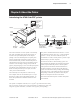
Chapter 3: Setting up the Printer Chapter 3: Setting up the Printer Unpack the printer Check the packing list Save all packing materials in case you need to repack the printer for shipping or storage.
Chapter 3: Setting up the Printer 17 Remove the packing restraints Receipt cover Receipt cover Cardboard support Front cover Carriage Foam restraint Paper roll supports Sample paper roll Test printout 1 Open the front cover, remove the foam restraint holding the carriage (1). 2 Remove the cardboard support (2) from the slip path. 3 Open the receipt cover (3). A760-D100 10/04 4 Remove the test printout (4).
Chapter 3: Setting up the Printer Load or change the receipt paper Change the paper when either a colored stripe appears on the receipt paper or the printer’s on-line, paper status, error LED slowly flashes (indicating that 15 ± 10 feet of paper remains on the roll). Change the paper as soon as possible to avoid running out of paper part way through a transaction. If the on-line, paper status, error LED blinks fast, the paper is out. Change the paper immediately or data may be lost.
Chapter 3: Setting up the Printer 19 Installing or replacing the ribbon cassette Change the impact printer’s ribbon cassette if it is printing lightly or produces marks, lines or other inconsistent printing on the receipt. Note: You must use an approved TPG, Inc. ribbon cassette with the check flip option to prevent jamming or other ribbon problems.
Chapter 3: Setting up the Printer Choose a location Receipt cover 280 mm (11.0) Extended slip table 178 mm (7.0) 229 mm (9.0) 264 mm (10.4) 347 mm (13.7) The A760 printer takes up relatively little counter space and may be set on or near the host computer. With the RS-232C interface, you can place the printer up to 50 feet (with the USB interface up to 15 feet) from the host computer and power supply.
Chapter 3: Setting up the Printer 21 Connect the cables Cable connections are made at the back of the printer. Caution: Connect the cables to the printer before applying power. The host computer should always be turned off before connecting communication cables. Warning! When instructed to connect the USB cable from the host to the printer, be careful to plug it into the USB board connector only (A). Do not insert the USB cable into the Cash Drawer connector (B) on the left back of the printer.
Chapter 3: Setting up the Printer Communication cables The communication cable connects the printer to the host computer. If installing the RS-232C communication cable: RS-232C 9-pin communication connector panel Power 9-pin RS-232C supply communication connector connector RS-232C 25-pin or parallel communication connector panel USB connector (not used) Power supply connector 25-pin RS-232C communication connector 1 Turn off the host computer. 3 Secure the connector by tightening the screws.
Chapter 3: Setting up the Printer 23 If installing the Ethernet communication cable: Ethernet communication connector panel Ethernet connector Power supply connector 1 Host computer can remain on. 2 Plug the printer end of the Ethernet cable into the Ethernet connector port on the printer (A). Make sure the connector snaps firmly in place. 4 After you have connected the printer, you must set the printer internal parameters for Ethernet operation.
Chapter 3: Setting up the Printer Cable routing To prevent the printer from becoming unplugged accidentally, make sure the cables are routed as shown in the illustration below.
Chapter 3: Setting up the Printer *** A760 - Printer Config Menu *** *** A760 - Diagnostics Form *** Model number Serial number Paper type can be changed in the configuration menu. Paper types and grades available: Type 0 - Monochrome grades Kanzaki P-310 Type 1 - Two-color grades Kanzaki P-310 RB Type 4 - Two-color grades Kanzaki P-310 BB Type 5 - Two-color grades Kanzaki P-320 RB See page 48 and Programming guide for more information.
Chapter 3: Setting up the Printer This page intentionally left blank. A760 Two-Color Thermal/Impact Hybrid Printer: User Guide 189-9200303 Rev.
Chapter 4: Using the Printer 27 Chapter 4: Using the Printer Printing on forms or checks There are several types of transactions that may require the insertion of a form or check into the printer: • Check printing (printing the date, payee, and amount on the check face) • Credit card transaction (requiring a merchant verification or authorization slip) • Check endorsement Although the illustration below shows a check being inserted into the printer, these instructions apply to any type of form.
Chapter 4: Using the Printer Verifying and validating checks If the printer has the optional MICR check reader, checks are verified and then validated. If the printer also has the optional check flip feature, the printer is able to flip the check over and print on the front of the check. Note: To ensure that checks are properly verified and validated, they must be free of folds and wrinkles and inserted correctly into the MICR printer. Smooth a wrinkled or folded check for best performance.
Chapter 4: Using the Printer 29 Clearing check flip paper jams Check Check flip window door To clear a paper jam from the optional check flip assembly: 1 Look in the window of the check flip assembly. If the jammed check is visible, open the window and remove it (1). 2 If the jammed check is not visible in the window, open the front cover (2) and remove the jammed check from behind the check flip assembly. Front cover A760-D100 10/04 189-9200303 Rev.
Chapter 4: Using the Printer Printer configurations Printers are shipped with all the functions and parameters pre-set at the factory. Settings for various printer parameters can be changed. This menu is printed on the receipt and scrolls through instructions for selecting and changing user changeable functions or parameters. Note: When changing the paper type, you will need to either send the “Set paper type” (1D 81 m n) command or use the “Set Paper Types” selection from the configuration menu.
Chapter 4: Using the Printer 31 Ethernet option Ethernet settings can not be changed in the configuration menu. If printer is currently configured for Ethernet use, refer to the Diagnostic Form printout for current settings. To change the current Ethernet settings or to set printer for Ethernet, see “Ethernet terminology and setup”, page 14 of the Programming supplement.
Chapter 4: Using the Printer Configuring the printer The configuration menu allows you to select functions or change various settings for the printer. Instructions printed on the receipt, guide you through the processes. Note: When changing the paper type, you will need to either send the “Set paper type” (1D 81 m n) command or use the “Set Paper Type” selection from the configuration menu. See paper types available on page 48.
Chapter 4: Using the Printer 33 Communication interface To change the communication interface settings (except Ethernet), enter the configuration menu, select “Set Communication Interface” from the main menu and answer “Yes” to “SET INTERFACE TYPE?” printed on the receipt. Caution: Be extremely careful changing any of the printer settings to avoid inadvertently changing other settings that might affect the performance of the printer.
Chapter 4: Using the Printer Diagnostic modes To change the diagnostic modes enter the configuration menu, select “Set Diagnostic Modes” from the main menu and select one of the following modes: • Normal: normal operating mode of the printer. • Datascope: the receipt printer prints incoming commands and data in hexadecimal format to help troubleshoot communication problems. • Receipt test: the receipt printer prints two code pages to verify proper printing of the receipt.
Chapter 4: Using the Printer 35 Enable or disable receipt test mode The receipt test mode verifies proper receipt printing. Receipt test is enabled and disabled by selecting the “Diagnostic Modes” sub-menu of the configuration menu. See “Configuring the printer”, page 32 for instructions on how to enter the configuration menu. To run the Receipt test mode: To exit the receipt test mode: 1 Enable the receipt test mode in the configuration menu. 1 Enter the configuration menu again.
Chapter 4: Using the Printer Enable or disable check flip test mode The check flip test verifies that the check flip mechanism will flip an inserted check only. It does not read the check. Check flip test is enabled or disabled by selecting the “Diagnostic Modes” sub-menu of the configuration menu. See “Configuring the printer”, page 32 for instructions on how to enter the configuration menu.
Chapter 4: Using the Printer 37 Setting the printer emulations Printer emulations determine what commands are available to the printer. To change the printer emulations settings, select the “Emulations/Software Options” sub-menu of the main menu and answer “Yes” to “Set the Printer Emulations?” printed on the receipt. This will take you to the instructions for setting the printer emulation.
Chapter 4: Using the Printer Printer settings and functions To change the printer settings and functions, enter the configuration menu, select the submenu from the main menu and answer the questions printed on the receipt until you come to the instructions for selecting the printer settings. Caution: Be extremely careful changing any of the printer settings to avoid inadvertently changing other settings that might affect the performance of the printer.
Chapter 4: Using the Printer 39 Select the hardware options sub-menu to set: • Printhead setting • Power supply wattage (Max power) This setting is the printhead energy rating and must match the rating marked on the the front right of the thermal mechanism in the printer. Whenever a new thermal mechanism is installed, this setting must match the indicated energy rating on the mechanism. (See A760 Service Guide for replacing the thremal mechanism.
Chapter 4: Using the Printer Preventing overheating of the printhead There are restrictions on the duty cycle because of the heat generated by the thermal printhead when printing solid blocks (regardless of the length of the block in relation to the print line). The restrictions are ambient temperature, the percentage of time (measured against one minute) of continuous solid printing, and the amount of coverage.
Chapter 4: Using the Printer 41 Troubleshooting the printer The A760 ColorPOS® printer is a simple, generally trouble-free printer, however unexpected conditions my arise. For example, the power supply may be disconnected or the thermal printhead may overheat. The on-line, paper status, error LED on the operator panel may signal that something is wrong. The light on the front right side of the printer is used only to indicate when a form is inserted properly. It does not indicate an error.
Chapter 4: Using the Printer Printer beeps Condition Possible causes What to do Printer beeps in a single, double, or triple The printer has a problem with its pattern at first power on, the on-line, electronics. paper status, error LED blinks in the same pattern, and the printer won’t power up. Printer beeps during normal operation. manual. Contact a service representative.
Chapter 4: Using the Printer 43 On-line, paper status, error LED flashes Condition Possible causes What to do On-line, paper status, error LED is blinking. Receipt paper is out. Change the paper now. Do not run a transaction without paper. Data may be lost. Receipt paper is out. Change the paper immediately. See “Load and change the receipt paper” page 18. Receipt, front or flip cover is open. Close the cover. The printer will not operate with any of the covers open. The knife is jammed.
Chapter 4: Using the Printer Poor forms print quality Condition Possible causes What to do Printer starts to print, but stops while the form is being printed. Communication error or software error. Check the interface cable. Check that the software is working properly. Forms print is light or spotty. Form not inserted incorrectly. See “Printing on forms or checks” page 27. Impact printhead is dirty or defective. Contact a service representative. Improper internal cable connections.
Chapter 4: Using the Printer 45 Poor receipt print quality Condition Possible causes What to do Color print is light. Variations in paper. Increase energy level of printhead in “Color Density Adj” of the printer configuration menu (see “Configuring the printer” page 32 and the Programming Supplement). Inconsistant printing, no two-color print.
Chapter 4: Using the Printer Slip station, MICR and check flip problems Condition Possible causes What to do The optional MICR (Magnetic Ink Character Recognition) check reader does not read or misreads checks. The check is inserted improperly. Make sure the check is inserted properly with the MICR characters down. See “Verifying and validating checks” page 28. The check is fraudulent. Make sure that the check is not fraudulent.
Chapter 4: Using the Printer 47 Returning a printer Follow these instructions if you need to return a printer for servicing. 1 If you are sending the printer to TPG, Inc. for repair, call TPG, Inc. for a Return Material Authorization number (RMA#) at 1(877) 209-0156 in USA or email: support@TPGprinters.com, or go to the TPG, Inc. Web site at http://www.TPGprinters.com. Be prepared to answer questions concerning shipping and billing. Request an RMA process be sent to you, if required.
Chapter 5: Paper and Supplies Chapter 5: Paper and supplies Ordering from TPG, Inc. Printer parts, accessories, and small quantities of paper can be ordered directly from TPG, Inc. While the TPG, Inc. part numbers are listed here for your convenience, keep in mind that these numbers may change before this guide is outdated. To place an order or get more non-technical information, call your TPG, Inc. representative or the sales line at (800) 732-8950. TPG, Inc.
Chapter 5: Paper and Supplies Jujo Thermal LTD. P.O. Box 92 FIN–27501 Kauttua, Finland Voice: (358)2–8393–2900 Fax: (358)2–3893–2419 49 AF50KS–E3 (Standard) AP62KS–E3 (Standard) Mitsubishi Int’l Corp (USA) Voice: (212)605–2000 520 Madison Ave. Fax: (212)605–2597 New York, New York 10022-4223 P–5035 (Light) T–8051 (Standard) TP–8065 (Standard) OJI Paper Company Ltd.
Chapter 5: Paper and Supplies Power supply and power cords Other suppliers may use different part numbers. Item Type Number 55-watt power supply with attached cable to printer and U.S. power supply cord A760–K330 75-watt power supply with attached cable to the printer and U.S. power supply cord A760–K331 55-watt power supply, attached cable A760–K301 75-watt power supply, attached cable A760–K302 Power supply cord (to outlet) United States International (no plug) United Kingdom S.E.V.
Chapter 5: Paper and Supplies 51 Forms specifications The A760 prints on single- or multiple-part forms in the slip station (up to five-part forms). Forms and slips must meet the following requirements: • Front insertion (minimum): 51 mm (2.00") wide 68 mm (2.68") long • Multiple-part forms (up to five parts) should be no thicker than 0.40 mm (0.016") and a minimum thickness of 0.08 mm (0.003"). • Side insertion (minimum): 203 mm (8.0") wide 51 mm (2.
Chapter 5: Paper and Supplies MICR head Slip sensor Slip/LED sensor Slip side guide 19 mm (0.747) 8 mm (0.315) 6 mm (0.236) Slip edge Paper feed direction Paper holes and low reflection prohibited areas B The Slip/LED sensors use a reflective photo sensor. • Do not use paper that has holes or is translucent at the Slip/LED sensor location. (See “A” in above illustration.
Chapter 5: Paper and Supplies 53 Check specifications Check specifications for paper are defined by American Standards ANSI X9.13 and ANSI X9.18, and International Standard ISO 1004. • Minimum check size: 70 mm (2.75") wide x 152 mm (6.00") long • Maximum check size: 95 mm (3.75") wide x 222 mm (8.75") long MICR reader – additional information • The check must be flat and void of curls, folds, or wrinkles (especially at the edges).
Chapter 5: Paper and Supplies This page intentionally left blank. A760 Two-Color Thermal/Impact Hybrid Printer: User Guide 189-9200303 Rev.
Appendix A: USB Driver Installation 55 Appendix A: USB Driver Installation USB and the host system TPG, Inc. provides two USB solutions. If your application is designed to talk to the printer as an RS-232C device, we offer an RS-232C Emulation USB Driver. If your application is capable of talking to a USB device, we offer two Native USB Drivers; an TPG, Inc. vendor class and a Printer class. The RS-232C Emulation USB driver is compatible with PCs that run Windows 95 (OSR 2.
Appendix A: USB Driver Installation The native USB solutions The TPG, Inc. native USB solutions provide USB connectivity for applications that can talk directly to a USB port. This solution is comprised of two distinct versions: an TPG, Inc. vendor class USB and a USB Printer Class. TPG, Inc. vendor class USB version The TPG, Inc. vendor class USB solution provides a vendor-specific class USB interface. This solution works on the Windows 98, Me, 2000, and XP operating systems and requires an TPG, Inc.
Appendix A: USB Driver Installation 57 Installing a native driver continued... Download the Printer class native driver Printer drivers are available for download from TPG, Inc.’s corporate Web site. The host computer must have Internet access in order to download the drivers. Keep in mind that, as TPG, Inc. continues to improve its customer relations, the architecture of the Web site may change. 1 Using your preferred Web browser, go to http:// www.TPGprinters.com.
Appendix A: USB Driver Installation The RS-232C Emulation USB solution The TPG, Inc. RS-232C Emulation USB solution eliminates any cost associated with porting applications to USB by implementing a USB solution that emulates standard RS-232C serial communication. Application developers only have to direct their software to the virtual RS-232C serial port created by the TPG, Inc. RS-232C Emulation USB driver to use the printer.
Appendix A: USB Driver Installation 59 Check the installation After you are finished installing the drivers, you should check to make sure they were installed correctly. Windows 95/98/Me/XP/2000 Windows NT 1 Open the Device Manager window, as you did when initially checking for USB support. 1 Go to the Windows Start button and select Programs>InsideOut Networks Utilities>Edgeport Configuration Utility. 2 Scroll down to Universal Serial Bus controllers.
Appendix A: USB Driver Installation Configuring serial port number assignments There are three ways that the Edgeport utility assigns serial port numbers to the printer. The serial port assignments are controlled and stored in the host computer, not the printer. You can change the way assignments are made in the Edgeport utility.
Appendix A: USB Driver Installation 61 Uninstalling the drivers 3 Click the Uninstall button and follow the on-screen instructions. 1 Start the Edgeport utility. 2 Click the Advanced tab. A760-D100 10/04 189-9200303 Rev.
Appendix A: USB Driver Installation USB driver installation troubleshooting This section lists some conditions you may run into during and immediately after driver installation. If you think the condition may not be related to USB, look in Chapter 4: Using the Printer, “Troubleshooting the printer.” That section describes other USB conditions which may arise or may not be apparent until after installation. Additional information on most of the conditions below can be found within this appendix.
Appendix A: USB Driver Installation 63 This page intentionally left blank. A760-D100 10/04 189-9200303 Rev.
A760 Two-Color Thermal/Impact Hybrid Printer: User Guide 189-9200303 Rev.