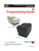
A776 (B780) Two-Color Thermal/Impact Hybrid Printer Programming Guide Printer without Imaging Printer with Imaging Includes CognitiveTPG LogoEZ® colorization information Made under one or more of the following U. S. patents: 4886381, 5579043, 5613787, 5651624, 5713678, 5752779, 5789916, 5800080, 5879090, 5887999, 5975776, 6027266, 6085973, 6089450, 6129465, 6155483, 6404452, 6486902, 6504331, 5749277, 6722754, 6739773, 6784909. A776-PG00001 Rev.
Federal Communications Commission (FCC) Radio Frequency Interference Statement Warning. Changes or modifications to this unit not expressly approved by the party responsible for compliance could void the user’s authority to operate the equipment. Note This equipment has been tested and found to comply with the limits for a Class A digital device, pursuant to Part 15 of the FCC Rules.
Contents i Contents Chapter 1: About this Guide............................................................................................................................... 1 How to use this Guide........................................................................................................................... 1 Where to find the basics.......................................................................................................................
ii Contents A776 Configurable Slip Commands..................................................................................................... 14 A776 Double High Slip Character Print.......................................................................................................... 14 A776 Slip Character Spacing.............................................................................................................................. 14 A776 Slip Minimum Units...................................
Contents iii Vertical and horizontal positioning ............................................................................................ 30 Text characteristics........................................................................................................................ 30 Graphics ......................................................................................................................................... 31 Status.................................................................
iv Contents Print and paper feed...................................................................................................................... 44 Print and feed paper one line............................................................................................................................. 44 Print and eject slip.................................................................................................................................................. 44 Print and carriage return...
Contents v Text strike-through mode (ColorPOS®)............................................................................................................ 63 Select font ID number........................................................................................................................................... 63 Select font style number......................................................................................................................................
vi Contents Real-time commands..................................................................................................................... 89 Preferred implementation................................................................................................................................... 90 Alternate implementation................................................................................................................................... 90 Rules for using real-time commands.......
Contents vii Exception table entry format............................................................................................................................. 120 Maintaining the exception table....................................................................................................................... 121 User data storage........................................................................................................................... 121 Write to user data storage.............
viii Contents Wait for Scan & Optionally Transmit............................................................................................ 138 Transmit Image.............................................................................................................................. 140 Eject from Scanner......................................................................................................................... 142 Free Image.................................................................
Contents ix Underline Off............................................................................................................................................................ 152 Double-High Off..................................................................................................................................................... 152 Double-High Font...........................................................................................................................................
x Contents A776 (B780) Programming Guide A776-PG00001 C 12/09
Chapter 1: About this Guide Chapter 1: About this Guide How to use this Guide This guide provides programming information on CognitiveTPG’s A776 (and B780) printer. It is written for tech-savvy users who are interested in customizing or adjusting printer functionality and is meant to be used with the A776/B780 ColorPOS® Two-Color Thermal Receipt/Impact Hybrid Printer User Guide.
2 Chapter 1: About this Guide A776 (B780) Programming Guide A776-PG00001 C 12/09
Chapter 2: Printer Status, Ethernet and Indicators 3 Chapter 2: Printer Status and Indicators The A776/B780 printer performs a number of diagnostics that provide useful information about the operating status of the printer. The following diagnostic tests are available. • Startup diagnostics, performed during startup cycle. Communication interfaces (except Ethernet) • Runtime diagnostics, performed during normal printer operation.
4 Chapter 2: Printer Status, Ethernet and Indicators For more information about See this section Accessing the remote diagnostic tallies “Command descriptions” in Chapter 5: Programming commands (Status commands: Transmit printer ID, remote diagnostics extension, Hexadecimal 1D 49 40 n) Ethernet terms and default setup For the printer to operate with Ethernet, a series of commands must be set within the printer.
Chapter 2: Printer Status, Ethernet and Indicators 5 Ethernet Default Setup To return the printer to the default settings, put the printer in the boot mode and hold down the feed switch until you hear the high-low-high tones (about 10 seconds). The default settings are: • • • • • • • Bootp Disabled DHCP Enabled Default IP 192.0.0.192 Net mask of 0.0.0.
6 Chapter 2: Printer Status, Ethernet and Indicators Indicators The printer communicates various conditions both visually, with two green lights or audibly, with a series of tones or beeps. The following table lists these indicators.
Chapter 3: Migrating to a new printer 7 Chapter 3: Migrating to A776 and B780 Migrating from existing CognitiveTPG printers The A776 printer is the fourth generation two station hybrid thermal/impact printer with feature enhancements designed to provide the most desirable options to the customer. This section is provided for those customers who would like to migrate from their existing CognitiveTPG printers to the A776 printer, while maintaining as much continuity as possible in the new application.
8 Chapter 3: Migrating to a new printer Moving from the A756 to the A776 (Thermal printhead differences) The following table details the list of commands whose behavior differs between the A756 printer and the A758, A760, and A776 printers. This is due to the physical differences of the 6 dots/mm head in the A756 and the 8 dots/mm head in the A758, A760 and A776. Command Description Difference between the A756 and the A776.
Chapter 3: Migrating to a new printer 9 Moving from the A756 to the A776 (Emulation commands) These commands are handled differently when the A776 is in A756 emulation mode. 1B 47 enable double strike (the difference is no parameter byte req’d) 1B 48 disable double strike 1B 4C... double density graphics command sequence Moving from the A756, A758, or A760 to the A776 (Slip differences) The impact station print zone on the A760 is 4.7 inches wide and the print zone on the A776 is 3.0 inches.
10 Chapter 3: Migrating to a new printer A776 Emulation Commands Set Printer ID Mode Code (Hexadecimal) 1F 03 0C n This command is ignored.
Chapter 3: Migrating to a new printer 11 Select A776 Narrow Slip Configuration Option to Ignore n Leading Spaces Code (Hexadecimal) 1F 03 25 08 n This command is available so A760 applications can ignore n leading spaces in a 42-column line of text. Range of n 0x00 < n < 0x20 hexadecimal 0 < n < 3 2 decimal • • • • n = 24 decimal is equivalent to printing the rightmost 42 columns of the A760 printzone (24 + 42 = 66). The first non-space in columns 1-n will stop ignoring leading spaces.
12 Chapter 3: Migrating to a new printer Select A776 (21 and 25-line) Rotated Slip Print Options Code (Hexadecimal) 1F 03 25 0C n • • • n 00 01 21-line rotated text print accommodates existing applications, which print 21 or fewer rotated lines (as read). The format will match the A756/A758/A760 exactly. 25-line rotated text print accommodates existing applications, which print between 22 and 25 rotated lines (as read). The format will not match the A756/A758/A760 exactly.
Chapter 3: Migrating to a new printer 13 Set Page Mode Margin Mechanical Adjustment Code (Hexadecimal) 1F 03 25 16 n · This command applies to both the A776 and the B780, although it is primarily implemented for B780 printers replacing existing A721 printers to match cashier check printing. · Default is 0. · Value is printed on the second diagnostic page. · Ranges for margin configurations: Margin Setting .5” .3” .
14 Chapter 3: Migrating to a new printer A776 Configurable Slip Commands A776 Double High Slip Character Print Code (Hexadecimal) Command 1F 03 26 01 n Enables or disables the 1B 21 10 command n 00 01 Double high slip character print command (1B 21 10) Disabled Enabled A776 Slip Character Spacing Code (Hexadecimal) Command 1F 03 26 02 n Enables or disables the 1B 20 n command n 00 01 Slip character right side spacing command (1B 20 n) Disabled Enabled A776 Slip
Chapter 3: Migrating to a new printer 15 Moving from A756/A758 to A776 Two-color Commands The following table details the list of commands related to two-color printing and ColorPOS® functionality that was not available on the A756 or the A758. CognitiveTPG ColorPOS® two-color and color interpreted commands Hexadecimal ASCII Description 1B 72 m ESC r m Set current color 41 1D 23 n GS # n Select current logo 68 1D 2A n1 n2 d1 . . .
16 Chapter 3: Migrating to a new printer LogoEZ® colorization commands Hexadecimal ASCII Discription Page 1F 03 16 f s p/r t US ETX SYN f s p/r t Set colorization 77 1F 03 17 a m s US ETX ETB a m s Set attribute mapping 79 Note: The new CognitiveTPG LogoEZ® colorization utility provides you a fast and easy way do get basic two-color and logos on your receipt without having to enter commands. Check out the CognitiveTPG Web site at www.CognitiveTPG.com.
Chapter 3: Migrating to a new printer 17 Migrating from the A721 (7221) printer to the B780 The B780 printer is a two station hybrid thermal/impact printer with feature enhancements designed to provide the most desirable options to the customer. This section is provided for those customers who would like to migrate from their existing CognitiveTPG printers to the B780 printer, while maintaining as much continuity as possible in the new application. Several commands exist to support such a migration.
18 Chapter 3: Migrating to a new printer · For text printing, these are the A721 internal dip switch settings: 3.2 3.3 3.4 Right Margin Text OFF OFF OFF .5” OFF OFF ON .3” OFF ON OFF .5” OFF ON ON .3” ON OFF -.1” ON ON -.1” Text Columns 33/40 33/40 35/42 35/42 35/42 42/51 · A721 internal dip switch 3.5 applies to the right margin in Page Mode printing. That is handled with another B780 configuration command.
Chapter 3: Migrating to a new printer 19 Select Two - Sensor Option for B780 Code (Hexadecimal) 1F 03 25 05 n This command sets the two-sensor option for the B780 mode. When enabled, two distinct slip sensor statuses are reported. n 00 01 Two-Sensor Option Disable two-sensor option Enable two-sensor option (default) Select Number of Lines of Validation for B780 Code (Hexadecimal) 1F 03 25 06 n This command sets the number of lines of validation that can be printed in B780 mode.
20 Chapter 3: Migrating to a new printer Select B780 Map Logo Option for B780 Code (Hexadecimal) 1F 03 25 10 n This command selects the B780 map logo option. This is available for A721 applications that rely on printing logos on the receipt. If this command is enabled, then the logos will be modifed by the printer firmware such that they print in an acceptable manner on the thermal receipt station.
Chapter 3: Migrating to a new printer 21 Select Cover Open Option for B780 Set Page Mode Margin Mechanical Adjustment Code (Hexadecimal) 1F 03 25 16 n · This command applies to both the A776 and the B780, although it is primarily implemented for B780 printers replacing existing A721 printers to match cashier check printing. · Default is 0. · Value is printed on the second diagnostic page. · Ranges for margin configurations: Margin Setting .5” .3” .
22 Chapter 3: Migrating to a new printer A776 (B780) Programming Guide A776-PG00001 C 12/09
Chapter 4: Programming the Printer 23 Chapter 4: Programming the Printer Overview of Printing Characteristics Commands control all operations and functions of the printer. This includes selecting the size and placement of characters and graphics on the receipt or the slip and feeding and cutting the paper. The programming commands have been organized, in order of hexadecimal code within functional groups. For this reason, “related” commands may not be listed adjacent to one another.
24 Chapter 4: Programming the Printer Character appearance The appearance of text can be changed using the following print modes: • Standard • Underlined • Compressed • Bold • Double-high • Reverse • Double-wide • Italic • Upside-down • Strike-through • Rotated • Scaled • Shading Receipt character specification Standard • Characters per inch: 15.6 • Characters per line: 44 • Cell size: 13 × 24 dots Compressed • Characters per inch: 20.
Chapter 4: Programming the Printer 25 Print zones Print zones for receipt station 80 mm paper Specifications of print zone for receipt station 80 mm paper: • 576 dots (addressable) @ 8 dots/mm, centered on 80 mm • Top margin to manual tear-off: 17.8 mm (0.70 inches) • Minimum margins for standard print: 2.0 mm (.079 inches) • Top margin to knife cut: 19.0 mm (0.
26 Chapter 4: Programming the Printer Print zones for slip station The slip station prints characters (standard and compressed pitch) and graphics in a print zone of 77mm (3.0”) wide on a slip or form. • Standard pitch: 42 characters (columns) per line • Compressed pitch: 51 characters (columns) per line • 21 rotated characters The print line height of 7x7 dot characters is 2.46mm (.097”). With three-dot spacing, the print line height is 3.53mm (.139”). See the following illustration (not to scale).
Chapter 4: Programming the Printer 27 Print Zones for Slip, Validation ! "## $ % & ' Validation Format The A776 has drop validation printing. The location of the first line of validation varies based on the table below: Number of lines of validation @ 7.2 lpi Distance from bottom of form to top of first print line 14 lines 2.7 inches 10 lines 2.0 inches 6 lines 1.
28 Chapter 4: Programming the Printer Rotated printing commands Three commands control the rotation of printing. The table shows the combinations of set/cancel upside down print, set/cancel rotated print (clockwise), and rotated print (counterclockwise). Rotated clockwise and rotated counterclockwise print commands are mutually exclusive: the setting of the last received command is effective. Unintended consequences may result when rotated clockwise is mixed with other commands.
Chapter 5: Programming commands 29 Chapter 5: Programming Commands Commands listed by function Commands in bold are ColorPOS® commands.
30 Chapter 5: Programming commands Print and paper feed Code (hexadecimal) Command Page 0A Print and feed paper one line 44 0C Print and eject slip 44 0D Print and carriage return 44 14 n Feed n print lines 44 15 n Feed n dot rows 45 16 n Add n extra dot rows 45 17 Print 46 1B 4A n Print and feed paper 46 1B 4B n Print and reverse feed paper 46 1B 64 n Print and feed n lines 46 1B 65 n Print and reverse feed n lines 47 1D 14 n Reverse feed n lines 47 1D 15 n Reverse
Chapter 5: Programming commands 31 1B 2D n Select or cancel underline mode 57 1B 3A 30 30 30 Copy character set from ROM to RAM 57 1B 3F n Cancel user-defined character 58 1B 45 n Select or cancel emphasized mode 58 1B 47 n Select double-strike 58 1B 48 Cancel double-strike 59 1B 49 n Select or cancel italic print 59 1B 52 n Select international character set 59 1B 56 n Select or cancel 90 degree clockwise rotated print 60 1B 74 n Select international character table 59 1B 7B
32 Chapter 5: Programming commands 1D 84 m n1 n2 d1…dx Download logo image 70 1D 86 m Monochrome shade mode 71 1D 87 m Color shade mode 71 1D 89 n m Logo print with color plane swap 72 1D 8B n m o Apply shading to logo 72 1D 8C n m Merge watermark mode 72 1D 90 m x y o p q Form and merge real-time surround graphic 73 1D 91 n Save graphics buffer as logo 74 1D 92 n Background logo print mode 74 1D 99 l m n o Apply margin message mode 75 1D 9A n m o Shade and store logo 75 1
Chapter 5: Programming commands 33 Bar codes Code (hexadecimal) Command Page 1D 48 n Select printing position for HRI characters 100 1D 66 n Select pitch for HRI characters 100 1D 68 n Select bar code height 100 1D 6B m d1…dk 00 or 1D 6B m n d1…dn Print bar code 100 1D 6B m nL nH d1... dn Print GS1 DataBar (formerly RSS), data length specified 103 1D 6B n d1...
34 Chapter 5: Programming commands User data storage Code (hexadecimal) Command Page 1B 27 m a0 a1 a2 d1…dm Write to user data storage 121 1B 34 m a0 a1 a2 Read from user data storage 122 1B 6A k Read from non-volatile memory 122 1B 73 n1 n2 k Write to non-volatile memory (NVRAM) 122 1D 22 n Select memory type (SRAM/flash) 122 1D 22 55 n1 n2 Flash memory user sectors allocation 123 1D 22 80 Expanded flash memory allocation 123 1D 22 81 n Select flash area 124 1D 40 n Erase user
Chapter 5: Programming commands 35 Image Commands Code (hexadecimal) Command 1D B0 Calibrate Scanner 132 1D B1 m n Configure/Change Image Transmission Port 133 1D B2 n Set Top Entry Startup Delay 133 1D B3 m p r Set Image Format Properties 133 1D C5 nL nH m d1-dn-1 Configure Binarization Methods and Attributes 134 1D B4 nL nH t0. . .
36 Chapter 5: Programming commands Command conventions The following information describes how each command is organized: Name: Name of command. ASCII: The ASCII control code. Hexadecimal: The hexadecimal control code. Decimal: The decimal control code. Value: A description of the command operands. Range: The upper and lower limits of the command operand. Default: The command operand default after printer reset. Description: Brief description and summary of the command.
Chapter 5: Programming commands 37 Close form ASCII: DC1 Hexadecimal: 11 Decimal: 17 Closes the feed roller and platen (forms compensation arm assembly). If the printer is reset or the Clear (0x10) is received, the feed roller and platen are opened. This command executes if the platen is already closed. This command is processed regardless of which station is selected.
38 Chapter 5: Programming commands Select peripheral device (for multi-drop) ASCII Hexadecimal Decimal ESC = n 1B 3D n 27 61 n Value of n: bits 0 and 1 only: 0 = printer only 1 = printer only 2 = peripheral device only 3 = printer and peripheral device both Default: printer only Selects the device to which the host computer sends data. Related Information When the printer is disabled by this command, it ignores transmitted data until re-enabled by same command.
Chapter 5: Programming commands 39 Select receipt or slip for printing; slip for MICR read ASCII Hexadecimal Decimal ESC c 0 n 1B 63 30 n 27 99 48 n Value of n: 1, 2, 3 Receipt selected 4 Slip selected 8 Validation station selected Default of n: 1 Selects the station for printing. When slip is selected, the printer waits for the paper to be inserted. When slip has already been selected and the selection is changed, the form is opened.
40 Chapter 5: Programming commands Select sensors to stop printing ASCII Hexadecimal Decimal ESC c 4 n 1B 63 34 n 27 99 52 n Value of n: Sensor status Default: 0 Bit of n Bit Function 0,1 Stop receipt on receipt low 4 Stop slip if trailing edge uncovered 5 Stop slip if leading edge uncover 7 Stop validation print if trailing edge uncovered (B780 only) Determines which sensor stops printing on the respective station.
Chapter 5: Programming commands 41 Generate pulse to open cash drawer ASCII Hexadecimal Decimal ESC p n p1 p2 1B 70 n p1 p2 27 112 n p1 p2 Value of n: 00, 48 (Decimal) = Drawer 1; 01, 49 (Decimal) = Drawer 2 Value of p1: 0–255 Value of p2: 0–255 Sends a pulse to open the cash drawer. Formulas The value for either p1 or p2 is the hexadecimal number multiplied by 2 msec to equal the total time.
42 Chapter 5: Programming commands Description When the monochrome paper type command (00) is set, this command is recognized and retained but has no effect. The monochrome paper selection (usually black) controls the output.
Chapter 5: Programming commands 43 4 = Two-color (blue/black) papers (Kanzaki P-320BB) 5 = Two-color (red/black) papers (Kanzaki P-320PB) Default: 0 (monochrome paper) This command will set the optimum parameter values in the thermal print engine control hardware for any defined monochrome or two-color paper chemistry. The m n parameters select paper category and formulation version, respectively.
44 Chapter 5: Programming commands Print test form ASCII Hexadecimal Decimal US t 1F 74 31 116 Prints the current printer configuration settings on the receipt. Disabled in page mode. Print and paper feed The print and feed commands control printing on the receipt and paper feed by the printer. Print and feed paper one line ASCII Hexadecimal Decimal LF 0A 10 Prints one line from the buffer and feeds paper one line. Carriage return/line feed pair prints and feeds only one line.
Chapter 5: Programming commands 45 Feed n dot rows ASCII Hexadecimal Decimal NAK n 15 n 21 n Value of n: Receipt - n/203 inch Slip n/72 inch Range of n: 0–127 in A756 emulation 0–255 in A758 emulation and A776 native mode Feeds paper n dot rows without printing. Receipt moves n rows if the print buffer is empty.
46 Chapter 5: Programming commands Print ASCII Hexadecimal Decimal ETB 17 23 Prints one line from the buffer and feeds paper one line. Print and feed paper ASCII Hexadecimal Decimal ESC J n 1B 4A n 27 74 n Value of n: Receipt - n/203 inch Slip n/144 inch Range of n: 0–255 Prints one line from the buffer and feeds the paper. On the receipt station, the line height equals the character height when n is too small. This does not apply to the slip station.
Chapter 5: Programming commands 47 Print and reverse feed n lines ASCII Hexadecimal Decimal ESC e n 1B 65 n 27 101 n Value of n: The number of lines on the slip station to be reverse fed. Range of n: 0 – 255 Prints one line from the buffer and reverse feeds the paper n lines on the slip station. The receipt station cannot be reverse fed.
48 Chapter 5: Programming commands Set column ASCII Hexadecimal Decimal ESC DC4 n 1B 14 n 27 20 n Value of n: Receipt - Slip Default of n: 1–44 = Standard pitch 1–56 = Compressed pitch 1–66 = Standard pitch 1–80 = Compressed pitch 1 Prints the first character of the next print line in column n. It must be sent for each line not printed at column one. The value of n is set to one after each line. Exceptions This command cannot be used with single- or double-density graphics.
Chapter 5: Programming commands 49 Set vertical line spacing ASCII Hexadecimal Decimal ESC 3 n 1B 33 n 27 51 n Value of n: Receipt - n/406 inch Slip - Range of n: n/144 inch 0 – 255 Default: Receipt - 0.13 inch (3.37 mm or 7.52 lines per inch, 3 extra dot rows) Slip 0.14 inch (7.20 lines per inch, 3 extra dot rows) Sets the line spacing for the receipt and for the slip. For the receipt, the space is set to n/406 inches. For the slip, the line spacing is set to n/144 inches.
50 Chapter 5: Programming commands Set relative print position ASCII Hexadecimal Decimal ESC \ n1 n2 1B 5C n1 n2 27 92 n1 n2 Value of n: To move the relative starting position right of the current position by n dots: n1 = Remainder after dividing n by 256 n2 = Integer after dividing n by 256 The values for n1 and n2 are two bytes in low byte, high byte word orientation.
Chapter 5: Programming commands 51 Select justification ASCII Hexadecimal Decimal ESC a n 1B 61 n 27 97 n Value of n: 0, 48 = Left aligned 1, 49 = Center aligned 2, 50 = Right aligned Range of n: 0–2, 48–50 Default: 0 (Left aligned) Specifies the alignment of characters, graphics, logos, and bar codes. The command can be enabled or disabled for the slip. Default is disabled for the slip on A776, and enabled on B780. Exception This command is valid only when input at the beginning of a line.
52 Chapter 5: Programming commands To set the Slip left margin to one inch at the default horizontal motion unit of 1/140 inches, send the four-byte string: GS L 140 0 Or, to set the left margin to two inches at the default horizontal motion unit of 1/140 units per inch, send the four-byte string: GS L 24 1 Exceptions: The command is effective only at the beginning of a line. This command is ignored if the line buffer is not empty.
Chapter 5: Programming commands 53 Or, to set the width of the printing area to two inches at the default horizontal motion unit of 1/203 units per inch, send the four-byte string: GS W 150 1 Where 2 inches = 406/203, and 406 = (1 X 256) + 150. Exceptions This command is effective only at the beginning of a line. If the setting exceeds the printable area, the maximum value of the printable area is used. The maximum printable area is 576 dots on the receipt and 420 dots on the slip.
54 Chapter 5: Programming commands Select pitch (column width) ASCII Hexadecimal Decimal ESC SYN n 1B 16 n 27 22 n Value of n: 0 = Standard pitch 1 = Compressed pitch Default: 0 (Standard pitch) Selects the character pitch for a print line. Formulas The following table provides the print characteristics for both pitches on the receipt and slip station. Pitch Receipt Columns Receipt CPI Slip Columns Slip CPI Standard 44 15.6 42 13.9 Compressed 56 20.3 51 17.
Chapter 5: Programming commands 55 Select print mode ASCII Hexadecimal Decimal ESC ! n 1B 21 n 27 33 n Value of n: Pitch selection (standard, compressed, double-high, or double-wide.) Value of n Bit Function 0 1 Bit 0 Pitch (See chart below) Standard pitch Compressed pitch Bit 3 Emphasized mode Canceled Set Bit 4 Double-high Canceled Set Bit 5 Double-wide Canceled Set Bit 7 Underlined mode Canceled Set 1 Bits 1, 2 and 6 are not used.
56 Chapter 5: Programming commands Define user-defined character set ASCII Hexadecimal Decimal ESC & s c1 c2 [character 1 data] ... [character k data] 1B 26 s c1 c2 [character 1 data] ... [character k data] 27 38 s c1 c2 [character 1 data] ...
Chapter 5: Programming commands 57 Each character is defined by 12 bytes (only bytes 2–11 are printed.) Each byte is one column (full- or half-dot column.) Overlapped dots are not printed. The data must contain [(c2 - c1 + 1) x 12] bytes. (See illustration.) Defines and enters downloaded characters into RAM or flash. The command may be used to overwrite single characters. User-defined characters are available until power is turned off or the initialize printer command (1B 40) is received.
58 Chapter 5: Programming commands Cancel user-defined character ASCII Hexadecimal Decimal ESC ? n 1B 3F n 27 63 n Value of n: Specified character code. Range of n: 32–255 Cancels the pattern defined for the character code specified by n. After the user-defined character is canceled, the corresponding pattern from code page 437 is printed. Exceptions This command is ignored if n is out of range or if the user-defined character is not defined.
Chapter 5: Programming commands 59 Exceptions The settings do not apply in page mode, However they can be set or cleared in page mode. Double-strike printing cannot be used with bit-images or downloaded bit-images. This command functions the same as A756 when the printer is in A756 emulation mode. In A776 native mode, the command takes a parameter to enable and disable it. Related information Printer output is the same as in emphasized mode.
60 Chapter 5: Programming commands Default: 0 (Code Page 437) Selects the character set to be used. Look in “Appendix B: Resident Character Sets” for the character sets. There are two codes for this command (see select international character set, 1B 74 n). Both codes perform the same function. Exception The character sets cannot be mixed on the same line. Related information This command may also be known as select character code table.
Chapter 5: Programming commands 61 Character width selection Hex Decimal Width 00 0 1 (normal) 10 16 2 (two times width) 20 32 3 (three times width) 30 48 4 (four times width) 40 64 5 (five times width) 50 80 6 (six times width) 60 96 7 (seven times width) 70 112 8 (eight times width) Character height selection Hex Decimal Height 00 0 1 (normal) 01 1 2 (two times height) 02 2 3 (three times height) 03 3 4 (four times height) 04 4 5 (five times height) 05 5 6
62 Chapter 5: Programming commands Turns on white/black reverse print mode. In white/black reverse print mode, print dots and non-print dots are reversed, which means that white characters are printed on a black background. When the white/black reverse print mode is selected it is also applied to character spacing which is set by right-side character spacing (1B 20). This command can be used with built-in characters and user-defined characters, but does not affect the space between lines.
Chapter 5: Programming commands 63 Text strike-through mode (ColorPOS®) ASCII Hexadecimal Decimal GS 0x85 m n 1D 8D n m 29 141 n m Value of m: 0 = retain same color as the character itself 1 = black 2 = paper color Value of n: standard cell height Default: n = 0 (off ) Prints a strike-through over characters. If the strike-through is as wide as the cell height, this will produce a cell that will be printed as a solid current color.
64 Chapter 5: Programming commands Save font ID number as default font at power up ASCII Hexadecimal Decimal GS 0xF0 0x03 1D F0 03 29 240 3 Save current font ID number as default font at power up. All characters will be printed from the downloaded font. Download font ASCII Hexadecimal Decimal GS 0xF0 0x80 followed by file 1D F0 80 29 240 128 This command is the sequence introducer for downloading existing files. The downloaded font is always stored in the permanent font area of flash.
Chapter 5: Programming commands 65 Define extended user-defined character set ASCII Hexadecimal Decimal US & s c1 c2 [character 1 data] ... [character k data] 1F 26 s c1 c2 [character 1 data] ... [character k data] 31 38 s c1 c2 [character 1 data] ...
66 Chapter 5: Programming commands Graphics These commands are used to enter and print graphics data and are described in order of their hexadecimal codes. Download BMP logo ASCII: ESC (+*.BMP file) Hexadecimal: 1B (+*.BMP file) Decimal: 27 66 77 (+*.BMP file) Value: Maximum width = 576 (640 for 8.5 mm paper) Maximum height = 512 Enters a downloaded BMP logo into RAM or flash. The downloaded BMP logo can be printed by using the print downloaded bit image (1D 2F m) command.
Chapter 5: Programming commands 67 Slip Station Value of m Mode No. of dots (vertical) No. of dots (horizontal) 0 8-Dot single-density 8 (72 DPI) 210 (70 DPI) 1 8-Dot double-density 8 (72 DPI) 420 (140 DPI) 32, 33 Not available on slip In single density, one byte (8-dots) is printed in each full dot column. In double-density, one byte is printed in each half/full dot column, but adjacent horizontal dots (overlapping dots) are not printed.
68 Chapter 5: Programming commands Select double-density graphics ASCII Hexadecimal Decimal ESC Y n1 n2 d1 ... dn 1B 59 n1 n2 d1 ... dn 27 89 n1 n2 d1 ... dn Equivalent to 1B 2A m=1 n1 n2 d1 ... dn Print Flash Logo ASCII Hexadecimal Decimal FS p n m 1C 70 n m 28 112 n m Print flash logo ID n using mode m. See command 1D 2F m for description of mode m. See command 1C 71 for description of n. The select slip command x/C must be disabled via 1F 03 38 00 to use this logo command.
Chapter 5: Programming commands 69 In the case of a new application using multiple logos, the select current logo (1D 23 n) command is used. After that, the printer no longer automatically erases the logo definition flash memory page when it fills with multiple definitions.
70 Chapter 5: Programming commands Print raster monochrome graphics (ColorPOS®) ASCII Hexadecimal Decimal GS 0x82 n1…..n72 (576 dots) for 80 mm paper, or n80 (640 dots) for 82.5 mm paper 1D 82 n1…..n72 (576 dots) for 80 mm paper, or n80 (640 dots) for 82.5 mm paper 29 130 n1…..n72 (576 dots) for 80 mm paper, or n80 (640 dots) for 82.5 mm paper Value and range of n: n1 to n72/n80 corresponds to one dot row data for a thermal receipt printer.
Chapter 5: Programming commands 71 Monochrome shade mode (ColorPOS®) ASCII Hexadecimal Decimal GS 0x86 m 1D 86 m 29 134 m This applies a selected shade density to all monochrome objects such as text and monochrome logos. The parameter m specifies the shading effect and has an initial value of 0 which signifies no effect. m specifies the percentage of shading, 0 <= m <= 100. m = 0 is the initial value and turns this mode off.
72 Chapter 5: Programming commands Logo print with color plane swap (ColorPOS®) ASCII Hexadecimal Decimal GS 0x89 n m 1D 89 n m 29 137 n m This command will print logo n. The command is ignored if a logo with index n has not been defined. If m = 0 the color(s) as defined in the logo is (are) used; if m = 1 and if the logo is a color one, then the two color planes (black and paper-color) in the logo are swapped.
Chapter 5: Programming commands 73 Form and merge real-time surround graphic (ColorPOS®) ASCII Hexadecimal Decimal GS 0x90 m x y o p q 1D 90 m x y o p q 29 144 m x y o p q This command will print a real-time graphic style designated by m. m = 0 rectangle, m =1 oval, m =2 ellipse (if printed in a square area the ellipse becomes a circle), m = 3 is a 5 point star, m = 4 is a free hand underline, m = 5 is a free hand ellipse and other values of m reserved for future styles.
74 Chapter 5: Programming commands Save graphics buffer as logo (ColorPOS®) ASCII Hexadecimal Decimal GS 0x91 n 1D 91 n 29 145 n This command will save all the raster data that is in the working graphics buffer (where surround graphics are formed) as a logo with index value n. This logo can then be used repeatedly for inserting different text. See the background logo print command.
Chapter 5: Programming commands 75 Apply margin message mode (ColorPOS®) ASCII Hexadecimal Decimal GS 0x99 l m n o 1D 99 l m n o 29 153 l m n o Value of l: l is a binary switch: 0 = disables margin message merging 1 = enable left margin message merging 2 = enable right margin message merging l > 2 ignore command Value of m: m is the ID (index) of the logo to be used in the merging. If a logo with index m does not exist or is wider than the print raster width then this command is ignored.
76 Chapter 5: Programming commands Logo print with knife cut ASCII Hexadecimal Decimal GS 0x9B m n 1D 9B m n 29 155 m n Value of m: 0= Standard size 1= Double wide 2= Double high 3= Double high/wide Value of n: 01 - FF (Hex) #dot rows = n x 24, n = 5 is the recommended setting Because the printhead and cutting knife are physically separated, it is necessary to advance the printed area of a receipt past the knife to avoid the last of the printing from being cut off.
Chapter 5: Programming commands 77 Set LogoEZ® colorization (ColorPOS®) ASCII Hexadecimal Decimal US ETX SYN f s p/t t 1F 03 16 f s p/t t 31 03 22 f s p/t t Value of f: 0= 1= 2= 3= 4= turn off all LogoEZ® colorization features link print logo after knife cut link watermark printing link margin message printing link logo print before cut Default: (Off ) 0 This command configures into EEPROM (permanent configuration switch setting) a set of features that allows placement of a color logo in the hea
78 Chapter 5: Programming commands Example: Activate watermark printing using logo #F1 (1F 03 16 02 s r) with “s” being the skip distance in dot rows before activation and “r” is the distance in mm between watermark repetitions. After executing a knife-cut command and the f = 1 steps, if s > 0, execute the following: • Skip “s” (feed paper) dot rows (15 s command) • Set watermark printing to “on” using logo F1 (execute merge watermark mode -1D 8C r F1 command).
Chapter 5: Programming commands 79 f = 4 link logo print before cut Prints a logo after the skip distance of “s” before a logo and “p” past a logo and performs a knife cut (1F 03 16 04 s p). Immediately before executing a knife-cut command, if s > 0, execute the following: • skip (feed paper) “s” dot rows (15 s command) • stop background merging (1D 9B 1 command).
80 Chapter 5: Programming commands Original attribute mapped table m bit on attribute mapped 0 Bold 1 Italic 2 Reverse 3 Underline 4 Double high 5 Double wide 6 Compressed print The following “s” bits and “m” bit 7 set the attributes that substitute for the mapped set: Attributes substituted table m bit on attributes substituted 7 Bold substituted s bit on attributes substituted 0 Italic 1 Reverse 2 Underline 3 Double high 4 Double wide 5 Compressed print 6 Alternate col
Chapter 5: Programming commands 81 Related information This command is utilized in the CognitiveTPG LogoEZ® utility. The utility can be used to pre-configure new printers with a default colorization set-up without requiring any application changes. The default set-up was designed to provide a general level of colorization features that would not affect the printer operation. You can expand beyond the default features of the utility by modifying the application at the host.
82 Chapter 5: Programming commands Status Status command introduction The A776 has three methods of providing status to the application. These methods are through batch status commands, real time status commands and unsolicited status mode. An application may use one or more of these methods to understand the current status of the printer. A brief description of each of these methods follows. Batch status commands – These commands are sent to the printer and stored in the printer’s buffer.
Chapter 5: Programming commands 83 Transmit paper sensor status ASCII Hexadecimal Decimal ESC v 1B 76 27 118 Values: Status Byte (A776 only) Bit Function 0 Signifies 1 Signifies 0 Receipt paper OK Low (only if paper low sensor is enabled) or receipt cover open 1 Covers open Both closed Either cover is open 2 Receipt paper OK Out 3 Knife OK Error or switch open 4 Always zero 5 Slip leading Not covered Covered edge sensor 6 Slip trailing Not covered Covered
84 Chapter 5: Programming commands Transmits the printer ID specified by n as follows: n Printer ID Specification ID (Hexadecimal) 1, 49 Printer model ID CognitiveTPG A776 0x2B (A776) 0x2A (A760) 0x28 (A758) 0x26 (A756) 0x2C (B780) 0x0A (A721) 2, 50 Type ID Installed options Refer to the table below 3, 51 ROM version ID ROM version 0x00 4, 52 Logo definition Logo definition Refer to table next column n = 2 or 50: Type ID Type ID (n = 2) Bit Off/On Hex D
Chapter 5: Programming commands 85 Transmit printer ID, remote diagnostics extension ASCII Hexadecimal Decimal GS I @ n 1D 49 40 n 29 73 64 n Values of n: Refer to table Range of n: 32–255 (not all defined but reserved) Preforms the remote diagnostic function specified by n. Eighteen remote diagnostic items are defined: eight printer ID items and ten printer tally items. Most of the diagnostic items are maintained in non-volatile memory (NVRAM), but some are maintained in read-only memory (ROM).
86 Chapter 5: Programming commands Value of n ASCII Hex Dec Remote diagnostic item Function é 82 130 Receipt lines tally Clear receipt lines tally to 0 â 83 131 Receipt lines tally Return receipt lines tally, preceded by n to identify Printer returns 10 bytes in above example: â00010000 ä 84 132 Knife cut tally, 8 digit ASCII numeric, max 99,999,999 Write to NVRAM à 85 133 Knife cut tally Write to NVRAM, and print on receipt to verify å 86 134 Knife cut tally Clea
Chapter 5: Programming commands 87 Value of n ASCII Hex Dec Remote diagnostic item Function » AF 175 Cover openings tally Return cover openings tally, returns 10 bytes B2 178 Max temperature tally Reset max temperature reached value | B3 179 Max temperature tally Return max temperature reached since it was reset, returns 10 bytes B4 180 Slip lines tally, 8 digit ASCII numeric, max 99,999,999 Write to NVRAM B5 181 Slip line tally Write to NVRAM, and print on receipt to verify
88 Chapter 5: Programming commands Printer status (n = 1 or n = 49) Bit Off/On Hex Decimal Status for transmit status 0 Off On 00 01 0 1 Receipt paper adequate. Receipt paper low. 1 Off On 00 02 0 2 Receipt paper adequate. Receipt paper low. 2 Off On 00 04 0 4 Receipt paper present. Receipt paper exhausted. 3 Off On 00 08 0 8 Receipt paper present. Receipt paper exhausted. 4 Off 00 0 Not used. Fixed to off. 5 Off 00 0 On 20 32 Slip leading edge sensor: paper present.
Chapter 5: Programming commands 89 Flash memory user sector status (n = 4 or n = 52) Bit Off/On Hex Decimal Status for transmit status 0 – – – Undefined. Fixed to off. 1 – – – Undefined. Fixed to off. 2 Off 00 0 User data storage write successful On 04 4 User data storage write failed, specified area not erased. Off 00 0 Flash logo area adequate, definition stored. On 08 8 Flash logo area not adequate for recent definition. 4 Off 00 0 Not used. Fixed to off.
90 Chapter 5: Programming commands Preferred implementation For a new application the GS (1D) sequences are recommended to avoid possible misinterpretation of a DLE (0x10) sequence as a clear printer (0x10 0, ASCII DLE NUL) command. An application using these GS (1D) sequences, does not need to distinguish for the printer between the new real time commands and the clear printer command.
Chapter 5: Programming commands 91 To guard against this situation, the application must determine the cause of a busy condition and take appropriate action or pace the real time commands to avoid filling the buffer. There is a minimum of 256 bytes available in the printer’s buffer when it goes busy.
92 Chapter 5: Programming commands 2 = Transmit RS-232C Busy Status Bit Status Hex Decimal Function 0 Off 00 0 Fixed to off. 1 On 02 2 Fixed to on. 2 Off 00 0 On 04 4 Receipt and cassette cover closed. Receipt or cassette cover open. 3 Off 00 0 On 08 8 Paper feed button is not pressed. Paper feed button is pressed. 4 Fixed to on. On 10 16 5 Off 00 0 On 20 32 Printing not stopped due to paper condition. Printing stopped due to paper condition.
Chapter 5: Programming commands 93 4 = Transmit receipt paper status Bit Status Hex Decimal Function 0 Off 00 0 Fixed to off 1 On 02 2 Fixed to on 2 Off 00 0 On 04 4 Receipt Paper adequate Receipt Paper low 3 Off 00 0 On 08 8 Receipt Paper adequate or Door Open Receipt Paper low or Door Open 4 On 10 16 Fixed to on 5 Off On 00 20 0 32 Receipt Paper present Receipt Paper exhausted 6 Off On 00 40 0 64 Receipt Paper present Receipt Paper exhausted 7 Off 00 0 Fixed
94 Chapter 5: Programming commands Real-time request to printer GS sequence DLE sequence ASCII Hexadecimal GS ETX n 1D 03 n 29 3 n DLE ENQ n 10 05 n 16 5 n Value of n: 1 = recover and restart 2 = recover and clear buffers 3 = cancel slip wait The printer responds to a request from the host specified by n. This command includes two sequences: GS and DLE. The operations performed depend on the value of n, according to the following parameters.
Chapter 5: Programming commands 95 Real-time printer status transmission ASCII Hexadecimal Decimal GS ENQ 1D 05 29 5 Transmits one byte status of the printer in real time. 0 Off 00 0 On 01 1 Paper adequate. Paper low (if paper low sensor enabled). 1 Off 00 0 On 02 2 Paper adequate. Paper low (if paper low sensor enabled). 2 Off 00 0 On 04 4 Both receipt and cassette door closed. Receipt or cassette door open. 3 Off 00 0 On 08 8 Not busy at the RS-232C interface.
96 Chapter 5: Programming commands Unsolicited status mode Select or cancel unsolicited status mode (USM) ASCII: GS a n Hexadecimal: 1D 61 n Decimal: 29 97 n Value of n: 0 turns mode off; any non-zero value turns mode on Default: 0 (USM disabled) Enables or disables automatic return of 4 status bytes whenever one or more of the listed changes occurs. This command is a batch mode command; that is, it is processed after all prior data in the input buffer has been processed.
Chapter 5: Programming commands 97 First Byte (printer Information) Bit Off/On Hex Decimal Status for USM 0 Off 00 0 Not used. Fixed to off. 1 Off 00 0 Not used. Fixed to off. 2 Off On 00 04 0 4 One or both cash drawers open. Both cash drawers closed. 3 Off On 00 08 0 8 Not busy at the RS-232C interface. Printer is busy at the RS-232C interface. 4 On 10 16 Not used. Fixed to on. 5 Off On 00 20 0 32 Receipt and cassette covers closed. Receipt or cassette cover open.
98 Chapter 5: Programming commands Third byte (paper sensor information) Bit Off/On Hex Decimal Status for USM 0 Off 00 0 On 01 1 Receipt paper adequate Receipt paper low (if paper low sensor enabled) 1 Off 00 0 On 02 2 Receipt paper adequate Receipt paper low (if paper low sensor enabled) 2 Off On 00 04 0 4 Receipt paper present. Receipt paper exhausted. 3 Off On 00 08 0 8 Receipt paper present. Receipt paper exhausted. 4 Off 00 0 Not used. Fixed to off.
Chapter 5: Programming commands 99 Fourth byte (paper sensor information) -- B780 Bit Off/On Hex Decimal Status for USM 0 Off 00 0 Slip paper selected On 01 1 Slip paper not selected Off 00 0 Possible to print on slip On 02 2 Not possible to print on slip On 00 0 Validation selected Off 01 1 Validation not selected On 00 0 Validation paper printable Off 01 1 Validation paper not printable 4 Off 00 0 Not used. Fixed to off.
100 Chapter 5: Programming commands Bar codes These commands format and print bar codes and are described in order of their hexadecimal codes. Select printing position of HRI characters ASCII Hexadecimal Decimal GS H n 1D 48 n 29 72 n Value of n: Printing position 0 = Not printed 1 = Above the bar code 2 = Below the bar code 3 = Both above and below the bar code Default: 0 (Not printed) Prints HRI (human readable interface) characters above or below the bar code.
Chapter 5: Programming commands 101 Rotated barcodes set with small modules (select bar code width command 1D 77 n , with n = 1 or 2) and PDF 417 barcodes in any orientation are printed at low speed, for better readability. Exceptions The command is only valid at the beginning of a line. Illegal data cancels the command. Values: First variation: String terminated with NUL character. Length k is not specified in command string; it depends on the bar code being printed. d1...
102 Chapter 5: Programming commands m Bar code d1...
Chapter 5: Programming commands 103 Print GS1 DataBar (formerly RSS), data length specified ASCII Hexadecimal Decimal GS k m nL nH d1... dn 1D 6B m nL nH d1... dn 29 107 m nL nH d1...
104 Chapter 5: Programming commands Print multiple barcodes ASCII Hexadecimal Decimal GS k 1D 6B FF n 29 108 255 All the individual barcode strings start with 1D 6B m, where m is the type of barcode. Use the same command to do multiple barcodes on one line.
Chapter 5: Programming commands 105 Select PDF 417 parameters ASCII Hexadecimal Decimal GS p a b c d e f 1D 70 a b c d e f 29 112 a b c d e f Value and Ranges: Value: Ranges: a, b = Description: The ratio of bar height to symbol length. a= height limit 1 to 10 b= width limit 1 to 100 c= rows limit 3 to 90 Number of rows in the matrix of code words. d= columns limit 7 to 30 Number of columns in the matrix of code words.
106 Chapter 5: Programming commands Each row has a left and right row indicator with a data region between. The left-most character in the top row of the data region is the total number of characters in the data region, excluding error correction characters. Characters within the data region are designed to be read from left to right, starting on the top row, immediately after the lengthdefining character. The maximum characters in the data region are 928.
Chapter 5: Programming commands 107 Slip page mode considerations Suggested command sequence to print bank check 1B 40 1B 63 30 04 1B 4C 1B 54 03 1B 57 00 00 00 00 90 01 80 05 Text and print commands 0C 1B 63 30 01 reset to power-on parameters select the slip select Page Mode select printing direction select page size (not necessary for default size) as required print the page and exit Page Mode eject the check and select receipt When switching be
108 Chapter 5: Programming commands Page mode configurations The original implementation of Page Mode on the slip station mapped thermal dots to impact dots, and sometimes produced output that was not acceptable to customers. Improvements have been made, and the improved impact Page Mode is the default configuration. It is printed out on the second diagnostic page, printed via 1F 74 1F 74 double command, or by holding down the paper feed button at power on until the second page starts to print.
Chapter 5: Programming commands 109 Select page mode ASCII Hexadecimal Decimal ESC L 1B 4C 27 76 Switches from standard mode to page mode. After printing has been completed either by the print and return to standard mode (FF) command or select standard mode (1B 53) the printer returns to standard mode. The developed data is deleted after being printed. For more information see page mode in this document.
110 Chapter 5: Programming commands Select standard mode ASCII Hexadecimal Decimal ESC S 1B 53 27 83 Switches from page mode to standard mode. In switching from page mode to standard mode, data buffered in page mode are cleared, the printing area set by set print area in page mode (1B 57) is initialized and the print position is set to the beginning of the line.
Chapter 5: Programming commands 111 Set print area in page mode ASCII Hexadecimal Decimal ESC W n1, n2 ...n8 1B 57 n1, n2 ...n8 27 87 n1, n2 ...n8 Range of n: 0–255 Default: n1–4 = n5 = n6 = n7 = n8 = Receipt Slip 0 0 64 144 2 1 64 128 2 5 Sets the position and size of the printing area in page mode.
112 Chapter 5: Programming commands Maximum area specification in page mode Maximizing the possible area in page mode consumes almost all of free RAM. Without any free RAM, bitmap rotations and enlargements cannot be performed. Use the user storage status command (1D 97 m n) to determine the amount of free memory. Exceptions The command is effective only in page mode.
Chapter 5: Programming commands 113 Formulas The distance from the current position is set to (nL + nH × 256) × vertical or horizontal motion unit] inches. The amount of movement is calculated only for the paper roll. When pitch n is specified to the movement downward: nL + nH × 256 = n When pitch n is specified to the movement upward (the negative direction), use the complement of 65536.
114 Chapter 5: Programming commands Formulas The waiting time is t × 100 ms for every macro execution. m specifies macro executing mode when the LSB (least significant bit) m = 0 The macro executes r times continuously at the interval specified by t when the LSB (least significant bit) of m = 1. Exceptions If this command is received while a macro is being defined, the macro definition is aborted and the definition is cleared. If the macro is not defined or if r is 0, nothing is executed.
Chapter 5: Programming commands 115 Transmit last MICR read ASCII: Hexadecimal: Decimal: ESC w R 1B 77 52 27 119 82 Resends the previously decoded MICR data (as if the parsing has not been defined) to the host. The return data is defined in the “Read MICR data and transmit” command (1B 77 01) without parsing and presents the data from the last MICR read since power-up or reset or indicates in the status that no read has yet occurred.
116 Chapter 5: Programming commands Examples of variable length field format specifications Account #, all characters in the field, keep spaces and dashes A Account #, all characters in the field, replace spaces and dashes xA Account #, maximum 12 characters, keep spaces and dashes 12A Account #, always 12 characters zero filled, remove spaces and dashes 012XA Other parameters Error number E One digit returned 0 Read OK 1 Read error: bad character, empty field invalid length, check di
Chapter 5: Programming commands 117 Sample parsing formats The following strings show various sample formats that you can use assuming they meet your parsing format needs. Included with the sample format is a description of the data that is returned to the application.
118 Chapter 5: Programming commands ESC w p T ‘/ A ‘/ C ‘/ S • All characters in the transit number • Field separator: / • All characters in the account number • Field separator: / • All characters in the check number • Field separator: / • Two-digit status • Final carriage return Notes: All parameters are ASCII characters, i.e. greater than or equal to 0x20, with the exception of a non-ASCII character enclosed in single quotes as a field separator.
Chapter 5: Programming commands 119 Once a parsing format is specified, the following values are returned: MICR characters ASCII Hexadecimal Numerics 0 ... 9 0x30 ... 0x30 Space 0x20 Dash 0x2D - Field separator* Country code* *As specified in the parsing parameter string Check serial number Parsing the check serial number Most banks print the check serial number in three easily recognizable spots.
120 Chapter 5: Programming commands In this example, without an exception table entry, the firmware would always pick the rightmost four-digit number as the check serial number following rule two above.
Chapter 5: Programming commands 121 After the right transit symbol are immediately the four characters of the check serial #, followed immediately by the ten characters of the account number.
122 Chapter 5: Programming commands Read from user data storage ASCII Hexadecimal Decimal ESC 4 m a0 a1 a2 1B 34 m a0 a1 a2 27 52 m a0 a1 a2 Value of m: 0 – 255 Reads m bytes of data from the user data storage flash page at the address specified. Returns m bytes to the application, followed by a carriage return (0Dh). The high order byte of the address (a0) ranges from 0 to n2–1, with n2 specified in the flash allocation command. If the flash allocation command has been used, the a0 = 0 always.
Chapter 5: Programming commands 123 n = 51 (ASCII n = 3) HEX 33 Loads user-defined characters to flash memory. An application must use this command to store user-defined characters in flash memory. Any user-defined characters defined following this command are stored in flash memory. A user-defined character cannot be redefined in flash memory. The flash memory page must be erased by an application before redefining user-defined characters.
124 Chapter 5: Programming commands Values and ranges: s = the number of dot rows in the character cell (maximum 64) c = the ASCII codes of the first (c1) and last (c2) characters respectively c1 = Hex 20–FF (20 is always printed as a space) c2 = Hex 20–FF (20 is always printed as a space) To define only one character, use the same code for both c1 and c2 j = s/8 = the number of bytes (vertically) in the character cell k = c2 – c1 + 1 = the number of characters to be defined in this command string [charac
Chapter 5: Programming commands 125 n = 50 (ASCII n = 2) HEX 32 This command erases all sectors available for user data storage. n = 51 (ASCII n = 3) HEX 33 This command erases all sectors available for permanent fonts. Erases a page of flash memory and sends a carriage return when the operation is complete. Related information See command “Flash memory user sectors allocation” (1D 22 55 n1 n2). See also command “Expanded flash memory allocation” (1D 22 80...) and “Select flash area” (1D 22 81 n).
126 Chapter 5: Programming commands This command returns the state of occupancy of available flash storage and user RAM. The printer response for each item is a 4 byte header, 0x1D 0x97 nL nH (number of bytes that follow in the response) and for each item a 4 byte structure: 1st m (type) byte, 2nd n index byte followed by a 2 byte CRC in Lo Hi order of the data string in that storage space.
Chapter 5: Programming commands 127 Return boot sector firmware part number ASCII Hexadecimal Decimal GS NULL 1D 00 29 0 Returns ACK (Hex 06) + 12 bytes ASCII string describing the flash memory boot sector firmware part number. Ex : 189–1234567A Exceptions Available only in download mode. Return segment number status of flash memory ASCII Hexadecimal Decimal GS SOH 1D 01 29 1 Returns the size of the flash used. There may be 16 (1 Meg) or 32 (2 Meg) sectors in flash memory.
128 Chapter 5: Programming commands Erase all flash contents except boot sector ASCII Hexadecimal Decimal GS SO 1D 0E 29 14 Causes the entire flash memory to be erased. The printer returns ACK if the command is successful; NAK if it is unsuccessful. Exceptions Available only in download mode. Return main program flash CRC ASCII Hexadecimal Decimal GS SI 1D 0F 29 15 Returns the CRC calculated over the flash firmware code space. The format of the response is ACK .
Chapter 5: Programming commands 129 communications failed or that the write to flash failed. The alternatives seem to be to retry the block or halt loading and assume a hardware failure. Related information Available only in download mode. Reset firmware ASCII Hexadecimal Decimal GS (SPACE) 1D FF 29 255 Ends the load process and reboots the printer. Before executing this command, the printer should have firmware loaded and external switches set to the runtime settings.
130 Chapter 5: Programming commands Set Gateway ASCII Hexadecimal Decimal Default: US BS ETX n1 n2 n3 n4 1F 08 03 n1 n2 n3 n4 31 8 3 n1 n2 n3 n4 none Sets the printer to the gateway having the IP address value specified by the values n1 to n4. A gateway, even when the printer is on another subnet, is not always needed. The printer initiates no connection and obtains the gateway address from the host packets.
Chapter 5: Programming commands 131 DHCP (auto-configuration) ASCII Hexadecimal Decimal US BS BS n1 1F 08 08 n1 31 8 8 n1 n1 = 0: n1 = 1: disabled enabled Default: enabled Enables or disables the use of DHCP at power-up to obtain an IP address. If no address is found within two minutes, DHCP obtains the default IP address.
132 Chapter 5: Programming commands Imaging Commands In these descriptions, the commands and parameters are given in hexadecimal unless otherwise noted.
Chapter 5: Programming commands 133 Configure/Change Image Transmission Port Hexadecimal: 1D B1 m n Parameters: m = 0 (default) after scanning, status + image file goes to the port issuing the scan or transmit function; = 1 all image transmissions go only to a 2nd channel Ethernet port. N = 0 indicate that this configuration is temporary (till powered off, default, or n = 1 selection is also retained in non-volatile memory.
134 Chapter 5: Programming commands r specifies the number of saved gray levels = scale resolution (default value = 0) as follows: Value Definition 0 No change from previous setting 1 Minimal noise cleaning preserving 128 gray levels 2 Low Standard noise cleaning preserving 64 gray levels 3 High Standard noise cleaning preserving 32 gray levels 4 Maximum noise cleaning preserving 16 gray levels 5 No noise cleaning and full 256 gray level as captured is preserved, default Return: None Descrip
Chapter 5: Programming commands 135 Define/Update Application Tag Values Hexadecimal: 1D B4 nL nH t0 . . .tm Parameters: n is the total byte count size of user TagData structures, each structure is similarly defined in the TIFF specification: 2 byte tag value, followed by a 2 byte type value, followed by a 2 byte count of byte length (note: this differs from TIFF directory entry), followed by the object. If the object is a string type, this would be the string itself; max length of each string is 127.
136 Chapter 5: Programming commands Decimal Value Definition 297 Reserved for FW Page Number & Number of Pages p1= bottom scanner, p2= top scanner; these are saved as type = two short integers 305 Application supplied string: Software = version description 306 FW supplied Date & 24 Hour Time of scan: 20 char YYYY:MM:DD:HH:MM:SS; must be application initialized to start FW time stamping 33432 Application supplied string: Copyright 65000 Reserved for FW auto generated int FileIndex value 65001
Chapter 5: Programming commands Value 137 Definition Decimal Meaning 8 No stored document 9 Bottom side only 10 Top side only 11 Internal interface timeout error 12 Internal interface other error 16 No bottom image 17 No top image 18 Unsupported format 19 Tag block full m Active Scanning command entry points: 0=no outstanding scan; 1=slip entry; 2=top entry; 3=waiting at both n Sensors currently covered / closed: none = all bits off; bit0 = imager rear detect; bit1 = imager front d
138 Chapter 5: Programming commands Real-Time Error Status Hexadecimal: 10 04 03 Parameters: None Return: 1 byte to be interpreted as follows: Bit Meaning 0 Fixed to 0 1 Fixed to 1 2 1 = jam in path 3 1 = knife error 4 Fixed to 1 5 1 = unrecoverable error 6 1 = a/d out of range error 7 Fixed to 0 Description: This immediately returns one byte of imager status.
Chapter 5: Programming commands Value Definition 1D Command return indicator 49 Image Scanner B8 Imaging function = wait for scan s Standard imaging status Decimal Meaning 0 OK 1 Jam detected 2 Wait for scan document cancelled 3 Imager cover open 7 Unrecoverable hardware error 8 No stored document 9 Bottom side only 10 Top side only 11 Internal interface timeout error 12 Internal interface other error 16 No bottom image 17 No top image 18 Unsupported format 19 Tag bloc
140 Chapter 5: Programming commands Description: If a document is present in the imager that has already been imaged, it is ejected out the imager back. When a document is presented at the appropriate entry point, scan and save the front and back image into the image buffer. Assign the next free FileIndex numbers so that both sides can be identified for subsequent image retrieval. This command waits for a document to be placed at an image source insertion position.
Chapter 5: Programming commands 141 Return: This uses the message structure/protocol transmission format that matches Scan & Transmit except for the command ID code: Value Definition 1D Command return indicator 49 Image Scanner B9 Imaging function = transmit s Standard imaging status Decimal Meaning 0 OK 1 Jam detected 2 Wait for scan document cancelled 3 Imager cover open 7 Unrecoverable hardware error 8 No stored document 9 Bottom side only 10 Top side only 11 Internal interf
142 Chapter 5: Programming commands If the image file return port is RS232, then the header and attached image file are transmitted under the settings of the Configure RS232 File Transmit parameters. XON-XOFF will not work for transmission of image.
Chapter 5: Programming commands 143 Free Image Hexadecimal: 1D BB nL nH Parameters: nL nH is the FileIndex of the image buffer space to be released. Return: 1D 49 BB s nL nH, where nL nH is the count of typical images that can be stored in free space in circular buffer order. S = 0 means buffer space was marked free, S = 1 no buffered image at the specified index. Description: This frees the space used by the image with FileIndex n for subsequent use in future image acquisition.
144 Chapter 6: DH emulation Configure Scan Options Hexadecimal: 1D C6 m n Parameters: m n Description 0 - Configure Imager default settings. Parameter n is ignored. 1 0 Disable auto eject on top scan jam (default). 1 1 Enable auto eject on top scan jam. 2 n Set maximum tag storage memory to n Kbytes. Default 4K. Range 2K to 64K. Out of range parameter defaults to 4K. Return: None Description: Configures scan options.
Chapter 6: DH Emulation 145 Chapter 6: DH emulation for B780 List of DH 4700 Emulation Commands This table lists the commands in numerical order according to their hexadecimal codes. The page number indicates where a complete description of the command can be found. Some commands listed are not implemented (they are identified as not implemented). If received, they are ignored and not sent to the print buffer as data.
146 Chapter 6: DH emulation List of DH emulation Commands continued: Hexadecimal Code Command Name Page 1B 46 Form In (Not Implemented) 149 1B 47 Select (Not Implemented) 149 1b 48 Double-High Font 152 1B 49 Either Form-In Sensor (Not Implemented) 149 1B 4A Both Form-In Sensors (Not Implemented) 149 1B 4B Busy Until Buffer Empty 149 1B 4C Clamp Delay 149 1b 50 Pitch Selection 152 1b 52 Upside-Down Off 152 1B 53 Print Speed (Not Implemented) 150 1b 5
Chapter 6: DH Emulation 147 List of DH 4700 Command Descriptions The command descriptions in this section are grouped in the following categories: · Printer Function Commands · Print Characteristics Commands · Graphics Commands · Printer Status Commands Within each group the commands are listed in numerical order according to their hexadecimal codes. Each command is described and the hexadecimal, decimal, and ASCII codes are listed.
148 Chapter 6: DH emulation 00 10 20 30 0 16 32 48 NUL Validation Lines/Inch DLE SPACE 0 00 40 0 NUL 64 Print Self Test NO @ (After setting temporary parameters) YES 8.0 6.9 6.0 5.3 ALT selects the previous pitch selection. Reset Printer Resets and initializes the printer. This command is processed immediately. All data in the buffer is lost. The printer reinitializes with the default DIP switch settings.
Chapter 6: DH Emulation 149 Document Clamp Close Closes the platen when the form has been detected and the time for the clamp delay is up. This command enables the Slip/Validation paper feed and disables the Receipt/Journal paper feed. Hexadecimal Decimal ASCII 1B 1C 27 28 ESC FS Form Eject Ejects the form from the validation station after it has been printed. Hexadecimal Decimal ASCII 1B 41 27 65 ESC A Download This command is not supported and is ignored if received.
150 Chapter 6: DH emulation Print Speed This command is not supported and is ignored if received. Hexadecimal Decimal ASCII 1B 53 27 83 ESC S Buffered Validate Opens the platen to allow a form to be inserted. Any data that is received after this command will not be printed until the form is detected. This command enables the Slip/Validation paper feed and disables the Receipt/Journal paper feed.
Chapter 6: DH Emulation 151 Character Set Selects the character set. The default character set is defined by the internal DIP switch.
152 Chapter 6: DH emulation Underline Print Activates the 9th wire on all character cells to underline all printable characters, including a space (blank) character. Hexadecimal Decimal ASCII 1B 43 27 67 ESC C Underline Off Turns off underline printing. Hexadecimal Decimal ASCII 1B 44 27 68 ESC D Double-High Off Turns off double-high printing. Hexadecimal Decimal ASCII 1B 45 27 69 ESC E Double-High Font Starts double-high printing.
Chapter 6: DH Emulation 153 Graphics Commands These commands are used to control the way graphics are entered or printed. They are listed in numerical order of their hexadecimal codes. Graphics Enters graphics printing mode which prints all available dots (uses all wires in the printhead). Any combination of dots may be printed in a graphics cell. Each graphics cell is eight dots wide by nine dots high, with nine bytes of data needed to define the cell (each byte defines the row of eight dots).
154 Chapter 6: DH emulation Each byte of data sent defines each column of the graphic to be printed. The first byte defines the column in the left margin, with the following bytes defining the columns to the right, for a total of up to 200 columns in the print line. The print line is printed unidirectionally. Graphics and text may be printed on the same line. Use three Vertical Tab commands (0B) to overlap printing by half a dot with the next line. Each vertical tab advances the paper by 0.
Chapter 6: DH Emulation A776-PG00001 C 12/09 155 A776 (B780) Programming Guide
156 Appendix A: Commands by hexadecimal code Appendix A: Commands listed by hexadecimal code Code (hexadecimal) Command Page 09 Horizontal tab 47 0A Print and feed paper one line 44 0C Print and eject slip 44 0C Print and return to standard mode 0D Print and carriage return 44 10 Clear printer 36 10 04 n Real-time status transmission (DLE sequence) 91 10 05 n Real-time request to printer (DLE sequence) 94 10 04 07 Real -time imager status 137 10 04 03 Real-time error status
Appendix A: Commands by hexadecimal code 157 Code (hexadecimal) Command 1B 2D n Select or cancel underline mode 57 1B 2E m n rL rH d1 … dn Print advanced raster graphics 67 1B 32 Set vertical line spacing to 1/6 inch 48 1B 33 n Set vertical line spacing 49 1B 34 m a0 a1 a2 Read from user data storage 1B 3A 30 30 30 Copy character set from ROM to RAM 57 1B 3C Return home 37 1B 3D n Select peripheral device (for multi-drop) 38 1B 3F n Cancel user-defined character 58 1B 40 Initi
158 Appendix A: Commands by hexadecimal code Code (hexadecimal) Command 1B 6A k Read from non-volatile memory (NVRAM) 1B 6D Perform partial knife cut (or code 1A) 37 1B 70 n p1 p2 Generate pulse to open cash drawer 41 1B 71 Release paper 41 1B 72 m Set current color 41 1B 73 n1 n2 k Write to non-volatile memory (NVRAM) 1B 74 n Select international character table 59 1B 75 0 Transmit peripheral device status 82 1B 76 Transmit paper sensor status 83 1B 77 01 Read MICR data and tr
Appendix A: Commands by hexadecimal code 159 Code (hexadecimal) Command 1D 23 n Select the current logo (downloaded bit image) 68 1D 24 nL nH Set absolute vertical print position in page mode 112 1D 2A n1 n2 d1…dn Define downloaded bit image 69 1D 2F m Print downloaded bit image 69 1D 3A Select or cancel macro definition 113 1D 40 n Erase user flash sector 124 1D 42 n Select or cancel white/black reverse print mode 1D 48 n Select printing position for HRI characters 100 1D 49 02
160 Appendix A: Commands by hexadecimal code Code (hexadecimal) Command 1D 89 n m Logo print with color plane swap 72 1D 8B n m o Apply shading to logo 72 1D 8C n m Merge watermark mode 72 1D 8D n m Text strike-through mode 63 1D 90 m x y o p q Form and merge real-time surround graphic 73 1D 91 n Save graphics buffer as logo 74 1D 92 n Background logo print mode 74 1D 97 m n User storage status 1D 99 l m n o Apply margin message mode 75 1D 9A n m o Shade and store logo 75 1D
Appendix A: Commands by hexadecimal code 161 1F 03 16 f s p/r t Set LogoEZ® colorization 77 1F 03 17 a m s Set LogoEZ® attribute mapping 79 1F 04 n Convert 6-dots/mm bitmap to 8-dots/mm bitmap 81 1F 05 n Select superscript or subscript modes 64 1F 08 00 Restore default settings 129 1F 08 01 n1 n2 n3 n4 Set IP address 129 1F 08 02 n1 n2 n3 n4 Set net mask 129 1F 08 03 n1 n2 n3 n4 Set gateway 130 1F 08 04 n1 n2 n3 n4 Set raw TCPIP port 130 1F 08 05 n1
162 Appendix B: Resident Character Sets Appendix B: Resident Character Sets Code Page 437 (US) A776 (B780) Programming Guide A776-PG00001 C 12/09
Appendix B: Resident Character Sets 163 Code page 737 (Greek) A776-PG00001 C 12/09 A776 (B780) Programming Guide
164 Appendix B: Resident Character Sets Code page 850 (Multilingual) A776 (B780) Programming Guide A776-PG00001 C 12/09
Appendix B: Resident Character Sets 165 Code Page 852 (Slavic) A776-PG00001 C 12/09 A776 (B780) Programming Guide
166 Appendix B: Resident Character Sets Code Page 857 (Turkish) A776 (B780) Programming Guide A776-PG00001 C 12/09
Appendix B: Resident Character Sets 167 Code page 858 (with Eurosymbol) A776-PG00001 C 12/09 A776 (B780) Programming Guide
168 Appendix B: Resident Character Sets Code page 860 (Portugese) A776 (B780) Programming Guide A776-PG00001 C 12/09
Appendix B: Resident Character Sets 169 Code page 862 (Hebrew) A776-PG00001 C 12/09 A776 (B780) Programming Guide
170 Appendix B: Resident Character Sets Code page 863 (French Canadian) A776 (B780) Programming Guide A776-PG00001 C 12/09
Appendix B: Resident Character Sets 171 Code page 865 (Nordic) A776-PG00001 C 12/09 A776 (B780) Programming Guide
172 Appendix B: Resident Character Sets Code page 866 (Cyrillic) A776 (B780) Programming Guide A776-PG00001 C 12/09
Appendix B: Resident Character Sets 173 Code page 1252 (Windows Latin 1) A776-PG00001 C 12/09 A776 (B780) Programming Guide
Appendix C: Electronic Journal 175 Appendix C: Electronic Journal The Electronic Journal feature is for use with an application that does not support electronic journal. The printer can be used to store a variety of transactions.
176 Appendix C: Electronic Journal Journal RAM buffer Journal data is temporarily buffered in RAM until the printer is triggered to write it to flash. At power up 4K bytes of RAM will be dynamically allocated. In the unlikely event that 4K bytes are not available, 2K will be allocated. If for some reason 2K bytes are not available, the electronic journal feature cannot be used. Allocation success or failure information is available to the interface via commands described below.
Appendix C: Electronic Journal 177 Printing and Erasing the Journal Flash Buffer: Operator Activation of Journal Print and Erase Enabled via 1F 03 2E 01. Disabled via 1F 03 2E 00. Enabled and disabled also via the config menu under the Emulation/Software Options sub-menu. Default is disabled. Option prints on diagnostic Form II: Journal print via Command Only (when disabled) Journal print via Operator (when enabled) Printing Journal via Operator (when enabled): 1) Open the receipt cover.
178 Appendix C: Electronic Journal 1F 0A C5 Return Journal Status Returns one byte of status. bit 0 = 0 >> Write to flash successful bit 0 = 1 >> Write to flash fail bit 1 = 0 >> RAM allocation for journal data successful bit 1 = 1 >> RAM allocation for journal data fail bit 2 = 0 >> Auto Journal Disabled bit 2 = 1 >> Auto Journal Enabled 1F 0A C6 Return Journal Flash Size Returns two 3-byte counts in hexadecimal notation, as n1 n2 n3 and m1 m2 m3.
A776-PG00001 Rev.