Pisces Digital ICS Repeater Product Manual
Edition Edition 1.2, D e cem ber 2 2, 201 2. Copyrights The information contained herein is the property of Coiler Corporation. No part of this document may be reproduced or transmitted in any form or by any means, electronic or mechanical and for any purpose without the prior written permission of Coiler. Copyrights © 2012. All rights reserved.
1. About This Manual This product manual is produced for the use of Coiler’s Pisces (PS) Digital ICS Repeater by Coiler personnel, licensees and customers. The Pisces Digital ICS Repeater has the most innovative technologies to simplify the installation process. Please first refer to the single sheet installation guide. This manual covers the functions of the Pisces (PS) in detail with OMT instructions (Section 8) and is needed only when the information on the single sheet installation is insufficient.
2. Table of Contents 1. About this Manual ....................................................................................3 2. Table of Contents .....................................................................................4 3. Safety Instructions ..................................................................................5 4. Package Contents & Parts Identification .........................................6 5. Product Introduction ...........................................................
3. Safety Instructions Any personnel involved in an installation, operation or service of the Coiler PS Digital ICS Repeater must understand and obey the following: 1. Coiler PS Digital ICS Repeaters must be used exclusively for its application described in this guide’s product introduction and nothing else. 2. For your safety, please be aware of power lines at all times during installation and use. Please make sure to take appropriate safety measures for protection.
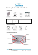
4. Package Contents & Parts Identification Standard Package: Accessories Information Model Name AC Adaptor EA10521B-060 Power Rating I/P: 100-240V~1.
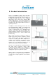
5. Product Introduction Pisces, or PS-2200 is Coiler’s Pico level ICS (Isolation Cancellation System) repeater. ICS is a breakthrough technology that cancels isolation up to 25dB and enables the Pisces to be equipped with built in donor and service antenna. With intuitive LED indicators, an average mobile phone user can simply plug in the power and place the PS-2200 at the best signal window location for optimal performance.
5.1 Product Features The PS Digital ICS Repeater represents some of the most innovative technologies from Coiler. The key technology that defines the PS is the Isolation Cancellation System (ICS). In addition, the Pisces also feature technologies such as Automatic Gain Adjustment (AGA), Automatic Gain Control (AGC), Auto Shut Down (ASD) and Auto Turn On (ATO). Each feature is described in details below. A. Isolation Cancellation System Isolation Cancellation System (ICS) is a complex technology.
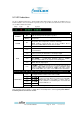
5.2 LED Indications The Pisces Digital ICS Repeater is designed with built-in LED indicators to simplify the installation process. Details indications can be found below. In general, the more green LEDs the better when it comes to the two sets of LEDs for RSSI and Isolation. Label Status On POWER Blinking Indication Calls are being made through the repeater. 3 seconds after no calls are being made, repeater would go into sleep mode. Overpower; Over temperature; Isolation; Unit faulty.
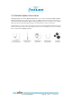
5.3 Available Optional Accessories Standard package of the Pisces Digital ICS Repeater is for one service area plug and play installation. Optional package includes one three meter cable, one 7dBi panel antenna (could be used as donor or service) and a wall mount bracket. With the optional packages, the user can easily use the external antenna to either locate a better signal location or use the antenna to service a second area.
6. Installation The installation of Pisces Digital ICS repeater without external antenna(s) is really just placing the unit next to the window and plugging in the power. However due to natural or manmade obstacles and the direction of the source signal, signal may not be sufficient for the Pisces to work properly. This section provides instruction on how to identify the best placement location and the application of Pisces with external antenna(s). 6.
6.3 Utilizing External Service Antenna This section refers to using components from the optional package. • • • • Remove the dummy load on MS CPL port (refer to Section 4 for base connections) and connect the 90° end of the 3 meter cable instead. Connect the 7dBi panel antenna to the other end of the 3 meter cable. Please make sure that all 5 Isolation LED are lid. Determine best location to mount the donor antenna to service a second area/room.
7. Testing Test the repeater’s performance by making phone calls using a mobile phone of the appropriate operator in various locations in the installation site. Ensure that the signal is available in the locations most distant from the service antennas and in the corners of the facility. In case there are any problems with these tests, please refer to the Troubleshooting section (Section 9) of this manual. For RF testing of various parameters, please download and install OMT for PS-2200.
8. Accessing the PS with Coiler OMT The Pisces Digital ICS repeater is designed to be a simply Plug & Connect DIY solution. The use of OMT would be strictly for changing of service frequency or to switch the unit into different test modes. To download the PS OMT, please visit Coiler’s FTP site below: ftp://ftp.coiler.com.tw/_ftp_/coilerclient/OMT/PS2200/ You will find the OMT file itself as well as the driver for the mini USB cable under this folder. This FTP site is password protected.
Once the OMT finishes the installation, you can locate it either in the “Start” menu under “All Programs” in the “Coiler” folder or you can find it on your desktop labeled “OMT”. You will NOT be able to access the PS with OMT at this point. Please continue to the next section before attempting launching OMT.
8.3 USB Driver Installation Unzip and run the “PreInstaller” file of the USB driver. Follow the on screen installation instruction to complete the driver installation. At this stage, the three part software/driver installation is complete. Before launching the OMT, you will need to find out which COM port the PS repeater uses. To find out which COM port to use, you would need to connect the PS to your computer in order to find out the exact COM port number. Once the PS and the computer are connected.
• Next you would need to find “Ports (COM & LPT)” in the hardware hierarchy chart. Expand “Ports (COM & LPT)” and locate “USB Serial Port” and note down the COM number (in the example below it is COM3, your setting may be different). You are now ready to launch the Coiler OMT.
8.4 OMT Login Now that you have all the software installed and know the COM port number, double click on the OMT software icon on your desktop or under coiler folder from the Start Menu. You will see the following screen.
8.5 Control, Monitor and Alarms This section indicates the working description of each function. A. Admin Screenshot - The administrator can press “Ctrl + F12” to see the detail polling information and save the information. Press “Polling” if you with to get the most updated repeater status. You may also set automatic polling by checking the “Auto Polling” box and indicate the interval in seconds.
Control Descriptions: DL Start Adjustable by 0.1MHz. Use the up and down arrow to adjust or simply type the frequency you wish in. DL Stop Always 15MHz difference from the DL Start Frequency. UL Start Will automatically be calculated base on DL Start Freq. UL Stop Will automatically be calculated base on DL Stop Freq. CH 1 Digital On/Off switch of the first 5MHz of your 15MHz selection. CH 2 Digital On/Off switch of the middle 5MHz of your 15MHz selection.
Monitor Descriptions: Input Power Indicating the input power of both DL and UL detected by the repeater. Gain Indicating the DL and UL gain of repeater. UL gain will display as N/A during UL standby mode (blue sleep button). Output Power Displays the DL and UL output power of the repeater. UL output power will display as Low during UL standby mode (blue sleep button). CH1 Displays the DL and UL working status of first 5MHz of your 15MHz selection.
B. Operator Screenshot The ICS function generates interference signal to the testing equipment and would distort the testing result. Hence a list of different test modes can be found under “admin” and “operator” account. Please select the appropriate test mode according to the testing parameters to ensure accurate result. Test Mode Purpose ICS ON Default setting. Always select this option to ensure proper functioning of PS. ICS UL Select this option to test UL standby mode.
C. User Screenshot User mode does not have ability to modify any setting. Only viewing of status is available.
9. Troubleshooting Please first refer to troubleshooting section of the Quick Installation Guide. Situation Solution There is still no signal after the • installation of the equipment. Ensure that the output power of the Adaptor is DC 6V / 6A and that green power LED is illuminated. • Ensure that all connections are tightly fastened. • Ensure that the outdoor signal level (RSSI) is sufficient. (Coiler recommends a signal strength greater than 80dBm, or three green RSSI LED).