Manuale d’installazione, uso e manutenzione Installation, use and maintenance manual Manuel d’installation, d'utilisation et d'entretien Installations-, Bedienungs- und Wartungsanleitung Manual de instalación, uso y mantenimiento Stufa a pellet mod - Pellet stove model - Poêle à granulés mod. Pelletofen Modell - Estufa de pellets mod. BEAUTY ** – BEAUTY LUX ** 484210551-M5_07/13 Hardware - M Leggere attentamente le istruzioni prima dell’installazione, utilizzo e manutenzione.
BEAUTY ** - BEAUTY LUX **
BEAUTY ** - BEAUTY LUX **
IT .............................................................................................................................................5-37 La Ditta COLA garantisce i propri prodotti secondo le norme attualmente in vigore , ad esclusione delle parti soggette a normale usura . Per le condizioni di garanzia rivolgersi all’importatore o al rappresentante autorizzato, il quale può integrare il periodo della garanzia obbligatoria con un periodo supplementare a sua totale ed esclusiva responsabilità.
1 2 3 4 AVVERTENZE GENERALI 1.1 Introduzione 1.2 Come utilizzare il manuale 1.3 Norme di sicurezza 1.4 Descrizione tecnica 1.5 Combustibile e uso consentito 1.6 Accessori in dotazione 1.7 Riferimenti normativi 1.8 Targa di identificazione 1.9 Messa fuori servizio della stufa 1.10 Istruzioni per richiesta di intervento e ricambi TRASPORTO ED INSTALLAZIONE 2.1 Imballo, movimentazione, spedizione e trasporto 2.2 Luogo d’installazione, posizionamento e sicurezza antincendio 2.3 Presa aria 2.
1 AVVERTENZE GENERALI 1.1 Introduzione Gentile Cliente , Desideriamo innanzi tutto ringraziarLa per la fiducia accordataci acquistando un nostro prodotto. La invitiamo a leggere e seguire attentamente i consigli contenuti in questo manuale d’installazione, uso e manutenzione al fine di poter sfruttare al meglio le qualità del prodotto.
1.4 Descrizione tecnica La stufa funziona esclusivamente a pellet e diffonde nell’ambiente un calore sano e sicuro. I sistemi di controllo automatici di cui è dotata garantiscono una resa termica ottimale ed una combustione completa , inoltre sono presenti dei sistemi di sicurezza atti a garantire un funzionamento sicuro sia per i componenti della stufa sia per l’utente.
Ingombri stufa pellet BEAUTY Legenda: 1-Griglie passaggio aria 2-Allacciamento cavo elettrico 3-Aspirazione aria comburente Ø 50 mm 4-Allacciamento tubo scarico fumi Ø 80mm 5-Sportello serbatoio pellet 6-Pannello comandi mod.
Ingombri stufa pellet BEAUTY LUX Legenda: 1-Griglie passaggio aria 2-Allacciamento cavo elettrico 3-Aspirazione aria comburente Ø 50 mm 4-Allacciamento tubo scarico fumi Ø 80mm 5-Sportello serbatoio pellet 6-Pannello comandi mod.
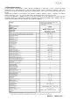
Per aprire la porta inserire la maniglia in dotazione e ruotare in senso orario Maniglia apertura-chiusura porta fuoco ; - Apertura: senso orario - Chiusura: senso antiorario 1.5 Combustibile e uso consentito Le stufe a pellet funzionano esclusivamente con pellet (pastiglie) di varie essenze di legno conformi alla normativa DIN plus 51731 o UNI CEN/TS 14961 o Ö-Norm M 7135 ovvero aventi le seguenti caratteristiche: min 4.8 kWh/kg (4180 kcal/kg) 680-720 kg/m3 max 10% del peso 6 +0.5 mm max 1.
Norma CEI EN 55014-1: Resistenza elettromagnetica – Requisiti per elettrodomestici, attrezzi elettrici e apparecchi elettrici simili – Parte 1: Emissione di disturbo ; Norma CEI EN 55014-2 : Resistenza elettromagnetica – Requisiti per elettrodomestici, attrezzi elettrici e apparecchi elettrici simili – Parte 2: Immunità ; Norma famiglia di prodotti ; Norma CEI EN 61000-3-2 : Limiti per le emissioni di corrente armonica ( Corrente ingresso ≤16 A per fase ) ; Norma CEI EN 61000-3-3 : Limitazione delle fluttua
Comignolo antivento Canna fumaria A = 300 mm B = 200 mm C = 1500 mm D = 200 mm Raccordo fumi Presa d’aria min. 100 cm² Base salva-pavimento Ogni installazione deve prevedere uno spazio tecnico di manovra di facile accesso per le manutenzioni periodiche . La stufa è fornita di 4 piedini regolabili per facilitare il posizionamento in presenza di pavimenti non perfettamente planari : per regolare l’altezza inclinare leggermente la stufa e ruotare il piedino interessato al livellamento .
All’interno dell’imballo della stufa viene collocato il coperchio opportunamente confezionato : aprire la confezione con cautela , controllare l’integrità del pezzo e al termine del piazzamento della stufa installarlo come segue : X-montare il coperchio dall’alto facendo coincidere le 4 sedi con i 4 antivibranti fissati sulla stufa. Y-bloccare il coperchio in posizione fissando con la staffa interna al serbatoio come da figura . X Y STAFFA DI ARRESTO COPERCHIO 2.
2.4 Scarico fumi di combustione Lo scarico fumi può essere fatto attraverso un allacciamento ad una canna fumaria tradizionale oppure ad un condotto esterno con tubo isolato o a doppia parete . I collegamenti di scarico fumi devono garantire un tiraggio minimo di 10 Pa in modo tale che in caso di mancanza temporanea di alimentazione elettrica l’evacuazione fumi venga assicurata .
2.6 Canalizzazione aria calda Il modello BEAUTY canalizzabile è dotata di due attacchi posteriori da 80 mm di diametro esterno per consentire la canalizzazione dei flussi d’aria calda generati da un ventilatore centrifugo interno alla stufa in scambio termico con le pareti della camera di combustione.
- Assicurarsi che l’impianto elettrico sia a norma, provvisto della messa a terra e dell’interruttore differenziale secondo le Norme vigenti. - Il cavo di alimentazione non deve mai toccare il tubo di scarico della stufa. 2.8 Schema elettrico 2.9 Pronto intervento Per ogni evenienza è consigliabile disporre di idonei dispositivi antincendio . Se si manifesta un incendio procedere come segue : - Scollegare immediatamente la presa di corrente . - Spegnere tramite l’uso di idonei estintori .
3.2 Sicurezza scarico fumi Nel normale funzionamento, la camera di combustione è in depressione garantendo la tenuta da eventuali perdite di fumo nell’ambiente.
- con la prima messa in funzione si possono riscontrare cattivi odori , pertanto si deve provvedere ad una buona aerazione della stanza, soprattutto durante il primo periodo di funzionamento ; il caricamento del serbatoio deve essere fatto esclusivamente con pellet, durante tale operazione evitare che il sacco venga a contatto con le superfici calde della stufa ; non inserire nel serbatoio nessun altro tipo di combustibile che non sia pellet conforme a quanto prescritto; l’apparecchio non deve essere utili
La Figura a fianco descrive il significato dei segnalatori di stato sulla parte sinistra del display . L’attivazione nel display di uno dei segmenti segnala l’attivazione del dispositivo corrispondente secondo l’elenco a fianco . 4.3 Accensione 4.3.
4.3.2 Fase di avvio Per accendere la stufa premere il pulsante ‘P4’ per 3 secondi : sul display comparirà la scritta ‘START’ . Questa fase è automatica ed è completamente gestita da controllo elettronico senza alcuna possibilità di intervenire sui parametri .
Temperatura ambiente Orologio Pulsante ‘P6’ Pulsante ‘P5’ Potenza impostata a 3 Finestra di dialogo Oltre alla regolazione della potenza si può può anche regolare la temperatura ambiente direttamente sul pannello comandi attraverso i pulsanti ‘P1’ e ‘P2’ : il display visualizza lo stato corrente del SET di temperatura . Per la ventilazione dell’aria calda , la stufa regola automaticamente la velocità in funzione della potenza impostata .
4.5 Spegnimento Per spegnere la stufa è sufficiente premere sul pulsante ‘P4’ per circa 2 secondi . La coclea è immediatamente arrestata e l’estrattore fumi viene portato a velocità elevata facendo apparire sul display la scritta ‘PULIZIA FINALE’ ; entrambi i motori di aspirazione fumi e di ventilazione dell’aria resteranno accesi fino a che la temperatura della stufa sarà scesa sufficientemente .
03 – stop 1 giorno 04 – lunedi prog 1 05 – martedi prog 1 06 – mercoledi prog 1 07 – giovedi prog 1 08 – venerdi prog 1 09 – sabato prog 1 10 – domenica prog 1 11 – start prog 2 12 – stop prog 2 13 – lunedi prog 2 14 – martedi prog 2 15 – mercoledi prog 2 16 – giovedi prog 2 17 – venerdi prog 2 18 – sabato prog 2 19 – domenica prog 2 20 – start prog 3 21 – stop prog 3 22 – lunedi prog 3 23 – martedi prog 3 24 – mercoledi prog 3 25 – giovedi prog 3 26 – venerdi prog 3 27 – sabato prog 3 28 – domenica prog 3
4.6.1 Menu 01 – regola ventole Le velocità delle ventole dell’aria è automatica e segue la potenza impostata. Se si desidera limitare il flusso d’aria calda è possibile impostare manualmente la velocità massima tramite la voce del menu 01, scegliendo un valore da 1 a 5 : ad esempio impostando il valore 3 , i ventilatori aumenteranno automaticamente la velocità , ma senza superare la velocità d’impostazione pari a 3.
Entrando nel sottomenu : PROGRAM WEEK-END è possibile abilitare , disabilitare e impostare le funzioni del cronotermostato nel week-end ( fine settimana : sabato – domenica ). Livello di menu Attivare la programmazione WEEK-END solamente dopo aver disattivato la programmazione settimanale . Al fine di evitare operazioni di avvio e spegnimento non voluti , attivare un solo programma per volta .
4.6.4 Menu 04 – scegli lingua Livello di menu Con questa selezione è possibile selezionare la lingua di dialogo tra quelle disponibili inserite nel menu e precisamente : - ITALIANO - FRANCESE - INGLESE - TEDESCO Finestra di dialogo 4.6.5 Menu 05 – modo stand-by Con la selezione ON nella modalità STAND-BY la stufa si spegne automaticamente dopo che la temperatura ambiente o la temperatura dell’acqua è rimasta superiore al valore di SET per un tempo prefissato.
Asta di comando in posizione ‘ tutto fuori ‘ 3° riferimento FLUSSO ARIA CALDA in direzione superiore e in canalizzazione Asta di comando in posizione 1° riferimento FLUSSO ARIA CALDA in direzione frontale VALVOLA di comando direzione flusso aria Dettaglio vista superiore uscita FLUSSO ARIA CALDA in canalizzazione Asta di comando in posizione intermedia - 2° rifer.
L’uscita canalizzata dell’aria calda standard di fornitura è verticale ; su richiesta del cliente è possibile inserire un kit valvola posteriore che consente la fuoriuscita dell’aria calda parzializzata sui tubi di canalizzazione destro e sinistro. Eventuali modifiche devono essere effettuate da personale autorizzato e competente ; le modifiche fatte in modo casuale possono provocare gravi danni all’apparecchio escludendo da qualsiasi responsabilità la ditta COLA . 4.
4.6.1 Sostituzione batteria Il telecomando viene fornito senza la batterie di alimentazione , esso funziona con una batteria posta nella parte inferiore del dispositivo e per il suo inserimento ed eventuale sostituzione è necessario procedere nel modo seguente : - Aprire il coperchio posto nella parte posteriore del telecomando ; - Sostituire la batteria modello p23ga da 12V nella sede rispettando la polarità ; - Chiudere il telecomando ; - Controllare il regolare funzionamento .
Il braciere deve appoggiare sul porta braciere e precisamente su tutta la fascia anulare senza presentare luci di passaggio aria. Braciere sporco Braciere pulito Porta Braciere pulito 5.2 Pulizia contenitore cenere Direttamente sotto il braciere - porta braciere è collocato il contenitore cenere . Per procedere alla sua pulizia è necessario aprire la porta fuoco ed aspirare con un idoneo aspiratore la cenere presente al suo interno ed eventuali residui di combustione.
6.1.1Smontaggio rivestimento BEAUTY ** Legenda: 1- Coperchio in maiolica 2- Sportello pellet 3- Sportello display controllo 4- Pannello laterale in acciaio verniciato 5- Frontalino in maiolica 6- Supporto frontalino superiore 7- Supporto frontalino inferiore 6.1.
6.2 Componenti interni della stufa Legenda : 1-Camera di combustione 2-Supporti dx-sx BEAUTY 3-Scambiatore in acciaio 4-Pareti laterali vermiculite 5-Deviatore superiore vermiculite 6-Parete posteriore vermiculite 7-Tubo canalizzazione aria calda 8-Gruppo aspirazione aria 9-Serbatoio pellet 10-Leva comando valvola 11-Perno di rotazione valvola 12-Valvola comando direzione flusso aria calda 13-Valvola di sicurezza Vista esplosa della camera di combustione e delle parti collegate rif.
6.3 Componenti elettrici Legenda: 1-Scheda elettronica 2-Vacuostato di controllo e sicurezza 3-Termostato sicurezza 4-Interruttore ON/OFF con fusibili 5-Sonda ambiente 6-Sonda fumi 7-Resistenza elettrica 8-Debimetro 9-Ventilatore centrifugo 10-Estrattore fumi 11-Pannello di comando mod.
7 RICERCA GUASTI 7.1 Gestione degli allarmi La presenza di un allarme si identifica con l’emissione di un segnale acustico (se attivato) e con un messaggio presente sul pannello di controllo. In caso di allarme spegnere la stufa, risolvere la causa che lo ha provocato e riavviare la stufa secondo la normale procedura illustrata nel presente manuale.
Segnalazione Anomalia Cause possibili Rimedi -La camera di combustione è sporca . -Il condotto fumi è ostruito. -La porta fuoco non è chiusa. -Le valvole antiscoppio sono aperte-inceppate . -Il vacuostato è difettoso . -Verificare la pulizia del condotto fumario e della camera di combustione . -Verificare la chiusura ermetica della porta . -Verificare la chiusura delle valvole antiscoppio . -Altre operazioni di ripristino devono essere condotte da un centro di assistenza .
8 ALLEGATI 36 BEAUTY ** - BEAUTY LUX **
BEAUTY ** - BEAUTY LUX **
1. GENERAL INFORMATION 1.1. Introduction 1.2. Using the manual 1.3. Safety rules 1.4. Technical description 1.5. Permissible use and fuel 1.6. Accessories supplied 1.7. Reference standards 1.8. Dataplate 1.9. Stove decommissioning 1.10. Instructions for requesting assistance and replacement parts 4.7 Thermostat – external chronothermostat 4.8 Hot air outlet flow adjustment 4.9 Idle period (end of season) 2. TRANSPORT AND INSTALLATION 2.1. Packing, handling, shipment and transport 2.2.
1 GENERAL INFORMATION 1.1 Introduction Dear Customer, First of all we wish to thank you for the trust placed in us by purchasing one of our products. Please read and carefully follow the advice given in this installation, use and maintenance manual in order make best use of the product. All the documents regarding the unit's certifications or declarations, in particular the Declaration of Conformity and Declaration of Performance, can be found through the website of the relevant trademark. 1.
1.4 Technical description The stove works exclusively on pellets, providing healthy and safe heat in the room. The stove's automatic control systems guarantee optimum heat output and complete combustion; there are also safety systems to guarantee safe operation for the stove parts and for the user. When correctly installed, the unit works in any outside climatic conditions, and in any case in critical conditions (strong wind, frost, etc.) the safety systems can cut in, shutting down the stove.
BEAUTY** pellet stove dimensions Key: 1 - Air grilles 2 - Power cable connection 3 - Combustion air inlet Ø 50 mm 4 - Flue pipe standard connection Ø 80 mm 4.
BEAUTY LUX** pellet stove dimensions Key: 1 - Air grilles 2 - Power cable connection 3 - Combustion air inlet Ø 50 mm 4 - Flue pipe standard connection Ø 80 mm 4.
Fire door opening-closing handle; - Opening: clockwise - Closing: anticlockwise To open the door, fit the handle supplied and turn it clockwise 1.5 Permissible use and fuel The pellet stoves work exclusively on pellets in different types of wood complying with Standard DIN plus 51731 or UNI CEN/TS 14961 or Ö-Norm M 7135 or having the following characteristics: Heat value Density Moisture Diameter: Ash percentage Length: Composition: Packing min. 4.8 kWh/kg (4180 kcal/kg) 680-720 kg/m3 max.
Standard CEI EN 55014-1: Electromagnetic resistance - Requirements for electrical appliances, electric tools and similar electric equipment - Part 1: Emission of interference; Standard CEI EN 55014-2 : Electromagnetic resistance - Requirements for electrical appliances, electric tools and similar electric equipment - Part 2: Immunity; Product family standard; Standard CEI EN 61000-3-2 : Limits for harmonic current emissions (Input current ≤16 A per phase); Standard CEI EN 61000-3-3 : Limitation of voltage
Antiwind grille A = 300 mm B = 200 mm C = 1500 mm D = 200 mm Flue Flue connection Inspection door on flue Air inlet min. 100 cm² T union with inspection cap Floor protection base Every installation must provide for an easily accessible technical space for periodical maintenance. The stove is provided with 4 adjustable feet to facilitate positioning on not perfectly flat floors. To adjust the height, tilt the stove slightly and turn the feet as required.
Packing is placed inside the lid of the stove packed accordingly: Carefully open the package, check the integrity of the piece and at the end of the placement of the stove to install it as follows: X-mount the top cover by aligning the 4 locations with 4 dampers set on the stove. Y-lock the lid in place to secure the bracket in the tank as shown X Y STOP BRACKET COVER 2.3 Air inlet The stove air inlet pipe or intake is located at the back and is round and 50 mm in diameter.
2.4 Fume exhaust The fumes can be exhausted through a connection to a conventional flue or an external duct with double wall or insulated pipe. The fume exhaust connections must guarantee a minimum draught of 10 Pa so that the evacuation of fumes is assured in case of a temporary power failure. - The installer must check the efficiency and state of the flue and its conformity with the local, national and European regulations.
2.6 Hot air ducting The BEAUTY ductable model has two rear connections of 80 mm external diam. for ducting the hot air flows generated by two centrifugal fans inside the stove in heat exchange with the side walls of the combustion chamber. To create the ducting system: - use pipes with internal diam.
2.7 Electrical connection Connect one end of the power cable to the rear socket of the stove, and the other to the wall socket. The voltage supplied by the system must match that specified on the stove dataplate and in the technical data section of this manual. During stove idle periods it is advisable to remove the power cable. - Make sure the electrical system is equipped with an earth and differential switch in accordance with the current Regulations.
3 STOVE SAFETY 3.1 Safety distance from flammable materials To prevent the risk of fire, stove positioning must respect a minimum distance from flammable materials, according to that given in the technical table of the manual and on the dataplate. Pay attention to the type of floor: for delicate and flammable materials it is advisable to use plates in steel or toughened glass as a support base (see section 2 - Transport and Installation).
4 STOVE USE 4.1 Introduction The pellet stove has the advantage of combining heat from a wood flame with the convenience of automatic management of temperature and the possibility of weekly programming of lighting and shutdown. Connection to an external thermostat and/or chronothermostat is possible for detecting the temperature in a different place from where the stove is installed.
On accessing the menu it is possible to obtain the various types of displays and carry out the available settings depending on the access level.
- At first startup, remove all the components (instructions/label) that could burn from the stove firebox and glass. - Any lightings done after long stove idle periods require the renewal of any pellets that have been inside the hopper for a long time, in being a damp fuel no longer suitable for combustion, and complete cleaning of the combustion chamber. 4.3.2 Startup stage To light the stove, press the button ‘P4’ for 3 seconds: the message ‘START’ will appear on the display.
4.4 Work stage After the 'STARTUP' stage, the stove goes to the 'WORK' mode which represents the normal operation mode. The user can adjust the heat output from the max. value of 5 to a min. of 1 with the buttons ‘P5’ and ‘P6’. Clock Room temperature Button ‘P6’ Button ‘P5’ Output set to 4 Dialogue box As well as adjusting the heat output, it is also possible to adjust the room temperature directly on the control panel with the buttons ‘P1’ and ‘P2’: the display shows the current SET temperature status.
4.5 Shutting down To shut down the stove, just press the button 'P4' for about 2 seconds. The auger is stopped immediately and the fume extractor is brought to high speed, with the message 'FINAL CLEANING' displayed; both fume extraction and air ventilation motors remain on until the stove temperature has lowered sufficiently. Clock Room temperature Dialogue box Button ‘P4’ Output At the end of the operation the message 'OFF' appears in the dialogue box.
09 – Saturday prog 1 10 – Sunday prog 1 11 – start prog 2 12 – stop prog 2 13 – Monday prog 2 14 – Tuesday prog 2 15 – Wednesday prog 2 16 – Thursday prog 2 17 – Friday prog 2 18 – Saturday prog 2 19 – Sunday prog 2 20 – start prog 3 21 – stop prog 3 22 – Monday prog 3 23 – Tuesday prog 3 24 – Wednesday prog 3 25 – Thursday prog 3 26 – Friday prog 3 27 – Saturday prog 3 28 – Sunday prog 3 29 – start prog 4 30 – stop prog 4 31 – Monday prog 4 32 – Tuesday prog 4 33 – Wednesday prog 4 34 – Thursday prog 4 35
4.6.1 Menu 02 – set clock The electronic control device has a lithium battery mod. CR2032 of 3 Volt inside. It allows the internal clock with own autonomy; if the clock signal does not appear when the stove is off or when switching the stove again a series of “0000” appears, it means it has to be substituted and you need to call one of our service point authorised for its substitution. 4.6.
PROGRAMME 1 Menu level Selection Meaning Possible values Activation time Reference day Deactivation time PROGRAMME 2 Menu level Selection Possible values Meaning Activation time Reference day Deactivation time PROGRAMME 3 Menu level Selection Possible values Meaning Activation time Reference day Deactivation time PROGRAMME 4 Menu level Selection Possible values Meaning Activation time Reference day Deactivation time By accessing the submenu: WEEK-END PROGRAM it is possible to enable
4.6.4 Menu 04 – select language Menu level With this selection it is possible to select the dialogue language from those available entered in the menu, and namely: - ITALIAN - FRENCH - ENGLISH - GERMAN 4.6.5 Menu 05 – standby mode Dialogue box With the selection of STANDBY mode ( ON selection ) the stove shuts down automatically after the room temperature has remained above the SET value for a fixed time.
Control rod in position 3th reference HOT AIR FLOW in upper direction and in ducting Control rod in top position 1st reference HOT AIR FLOW in frontal direction Hot air flow direction control VALVE Detail view of upper output HOT AIR FLOW in ducting Control rod in middle position - 2nd ref.
4.8 Thermostat - external chronothermostat The unit controls the room temperature by means of its own digital thermostat whose function is to detect the temperature through a probe and lower the heat output when the set temperature is reached.
5 STOVE CLEANING Stove cleaning is very important to ensure correct operation and to prevent: blackening of the glass, poor combustion, deposits of ash and unburnt products in the brazier, reduced thermal efficiency. The stove must only operate with the fire door closed. The fire door seals must be checked periodically to prevent any air from entering; the combustion chamber and pellet duct work in a negative pressure and the fume exhaust in a positive pressure.
Every 1800 hours of operation, by means of a message 'SERVICE DUE', the stove signals the need for extraordinary maintenance (not under warranty) to be performed by qualified personnel who will carry out complete cleaning and reset the message. Any knocking or forcing can damage the fume extractor, making it noisy during operation; therefore it is advisable to have this operation carried out by qualified personnel. 5.
6.2 Removing the cladding Key: 1 - Cover tiled 2 - Door pellet 3 – Counter control display 4 - Side Panel in painted steel 5 - Front tiled 6 - Support upper front 7 - Support lower bezel 6.
6.
6.
7 TROUBLESHOOTING 7.1 Alarm management Alarms are indicated by an acoustic signal (if activated) and a message on the control panel. In case of an alarm, shut down the stove, eliminate the cause and restart the stove according to the normal procedure described in this manual. The alarms, with causes and cures, which can appear on the control panel are listed below: ALARMS - MESSAGES Signalling Fault Possible causes Cures -The stove does not start. -No power during the lighting stage.
Signalling AL 8 NO NEG PRESS AL 9 INSUFF DRAUGHT AL b AUG TRIAC ERROR WAITING COOL AIR FLOW METER FAILURE SERVICE DUE Fault Possible causes Cures -The combustion chamber is dirty. -The fume duct is obstructed. -The fire door is not closed. -The overpressure valves are open-stuck. -Faulty vacuum switch. -Check cleanness of the fume duct and combustion chamber. -Check hermetic closing of the door. -Check closing of the overpressure valves.
8 ENCLOSURES 69 BEAUTY ** - BEAUTY LUX **
BEAUTY ** - BEAUTY LUX **
1. RECOMMANDATIONS GÉNÉRALES 1.1. Introduction 1.2. Comment utiliser ce manuel 1.3. Règles de sécurité 1.4. Description technique 1.5. Combustible et usage prévu 1.6. Accessoires fournis 1.7. Normes de référence 1.8. Plaque d’identification 1.9. Mise hors service du poêle 1.10.Demande d’intervention et de pièces détachées 2. TRANSPORT ET INSTALLATION 2.1. Emballage, manutention, expédition et transport 2.2. Lieu d'installation, mise en place et sécurité anti-incendie 2.3. Prise d'air 2.4.
1 RECOMMANDATIONS GÉNÉRALES 1.1 Introduction Cher Client ! Nous vous remercions de la confiance que vous nous avez accordée en achetant ce produit. Nous vous invitons à lire et à suivre attentivement les conseils fournis par ce manuel d’installation, d'utilisation et d'entretien pour exploiter au mieux les qualités de cet appareil.
1.4 Description technique Le poêle fonctionne exclusivement à granulés et propage une chaleur saine et rassurante dans la pièce. Les systèmes de contrôle automatiques dont il est pourvu assurent un rendement thermique optimal et une combustion complète. Des systèmes de sécurité garantissent des conditions de sécurité pour l'utilisateur et la fiabilité des composants du poêle.
Dimensions du poêle à granulés BEAUTY Légende : 1 2 3 4 - Grilles de passage d'air Connexion du câble électrique Aspiration air de combustion, diamètre 50 mm Raccordement standard du tuyau d'évacuation des fumées Ø 80 mm 5 - Couvercle de réservoir à granulés 6 - Tableau de commande mod.
Dimensions du poêle à granulés BEAUTY LUX Légende : 1 2 3 4 - Grilles de passage d'air Connexion du câble électrique Aspiration air de combustion, diamètre 50 mm Raccordement standard du tuyau d'évacuation des fumées Ø 80 mm 5 - Couvercle de réservoir à granulés 6 - Tableau de commande mod.
Pour ouvrir la porte insérer la poignée fournie et tourner en sens horaire Poignée d'ouverture-fermeture porte de foyer ; - Ouverture : sens horaire - Fermeture : sens anti-horaire 1.
marquages, ainsi qu'aux méthodes d'essai correspondantes pour les essais de type d'appareils fonctionnant aux granulés de bois ; Norme CEI EN 60335-1 : Appareils électrodomestiques et analogues - Sécurité - Partie 1 ; Norme CEI EN 60335-2-102 : Appareils électrodomestiques et analogues - Sécurité - Partie 2 ; Norme CEI EN 55014-1: Compatibilité électromagnétique – Exigences pour les appareils électrodomestiques, outillages électriques et appareils analogues - Partie 1 : Émission ; Norme CEI EN 55014-2 : Com
Si le conduit de fumée doit traverser des plafonds ou des poutres de bois ou de tout autre matière combustible, celui-ci doit être dûment isolé selon la réglementation encadrant l'installation du poêle à granulés. La distance minimale de sécurité devant le poêle pour les objets inflammables est de 1,5 m.
L'emballage est placé à l'intérieur du couvercle du poêle emballés en conséquence: Ouvrez avec précaution le paquet, de vérifier l'intégrité de la pièce et à la fin de la mise en place du poêle de l'installer comme suit: X-monter le capot supérieur en alignant les 4 emplacements avec 4 amortisseurs fixés sur la cuisinière. Y-verrouiller le couvercle en place pour fixer le support dans le réservoir, comme illustré X Y ARRÊT DE COUVERTURE SUPPORT 2.
2.4 Évacuation des fumées de combustion Les fumées peuvent être évacuées par un conduit de fumée traditionnel ou par un conduit extérieur isolé ou à double paroi. Les conduits de raccordement doivent garantir un tirage minimum de 10 Pa de manière à pouvoir assurer l'évacuation des fumées en cas de coupure de courant momentanée. - Il est recommandé à l’installateur de vérifier l’efficacité et l’état de la cheminée, ainsi que la conformité à la réglementation locale, nationale et européenne en vigueur.
2.6 Canalisation air chaud Le modèle BEAUTY ** canalisable est équipé de deux raccords arrière de 80 mm de diamètre extérieur pour permettre la canalisation des flux d'air, générés par les ventilateurs centrifuges incorporés dans le poêle, en échange thermique avec les parois latérales de la chambre de combustion.
- S'assurer que l'installation électrique est réalisé avec une connexion de mise à la terre du poêle et un l'interrupteur différentiel conformément aux textes réglementaires et règles de l'art en vigueur. - Le câble d'alimentation ne doit jamais entrer en contact avec le conduit d'évacuation des fumées du poêle. 2.
3.2 Sécurité pour l'évacuation des fumées Normalement, la chambre de combustion fonctionne en dépression et garantit l'étanchéité contre toute fuite de gaz dans l'environnement.
- - ne pas introduire dans le réservoir d’autres types de combustible que les granulés conformes aux prescriptions ; ne pas utiliser le poêle comme incinérateur de déchets ; la porte du foyer doit toujours être fermée quand le poêle est allumé ; les joints de la porte du foyer doivent être contrôlés régulièrement pour éviter toute infiltration d’air ; le poêle doit toujours être propre pour garantir un bon fonctionnement et un rendement thermique efficace : nettoyer le brasier à chaque chargement de granu
Bouton Description Augmentation de la température Modalité Action PROGRAMMATION FONCTIONNEMENT/OFF Diminution de la température PROGRAMMATION FONCTIONNEMENT/OFF Modifie/augmente la valeur de menu sélectionnée Augmente la valeur de la température du thermostat d'ambiance Modifie/diminue la valeur de menu sélectionné Diminue la valeur de la température du thermostat d'ambiance Permet d'accéder au menu Permet d'accéder au niveau de sous-menu suivant Réglage/menu PROGRAMMATION FONCTIONNEMENT ON
4.3.2 Mise en marche Pour allumer le poêle, appuyer sur le bouton ‘P4’ pendant 3 secondes : sur l'écran apparaîtra l'indication ‘START’. Cette phase est automatique et est complètement gérée par l'électronique de commande. Il n'est pas possible ici d'intervenir sur les paramètres.
En plus de la régulation de la puissance, il est possible aussi de régler la température ambiante directement sur le tableau de commande par les boutons ‘P1’ et ‘P2’ : sur l'écran apparaît alors l'état courant de la CONSIGNE (SET) de température. Pour la ventilation de l'air chaud, le poêle régule automatiquement la vitesse en fonction de la puissance préréglée.
Sur l'écran, dans la fenêtre de dialogue, apparaîtra l'indication ‘OFF’ au terme de l'opération. Pendant la phase d'extinction, il n'est pas possible de remettre en marche le poêle jusqu'à ce que la température des fumées n'est pas descendue en dessous d'une valeur prédéterminée pour une durée prédéfinie. Dans la fenêtre de dialogue apparaît alors l'indication ‘ATTENTE REFROID’. 4.
24 – mercredi prog 3 on / off 25 – jeudi prog 3 on / off 26 – vendredi prog 3 on / off 27 – samedi prog 3 on / off 28 – dimanche prog 3 on / off 29 – start prog 4 heure 30 – stop prog 4 heure 31 – lundi prog 4 on / off 32 – mardi prog 4 on / off 33 – mercredi prog 4 on / off 34 – jeudi prog 4 on / off 35 – vendredi prog 4 on / off 36 – samedi prog 4 on / off 37 – dimanche prog 4 on / off 01 – chrono week-end on / off 04 – program week-end 02 – start 1 03 – stop 1 04 – start 2 0
Niveau de menu Aller dans le sous-menu : PROGRAM JOUR, pour activer, désactiver et présélectionner les fonctions du chronothermostat journalier. Il est possible de régler deux phases de fonctionnement délimitées par les horaires prédéfinis selon le tableau suivant où le réglage OFF indique à l'horloge d'ignorer la commande.
PROGRAMME 4 Niveau de menu Sélection Signification Valeurs possibles Heure d‘activation Jour de référence Heure de désactivation Aller dans le sous-menu : PROGRAM WEEK-END, pour activer, désactiver et présélectionner les fonctions du chronothermostat dans le week-end ( fin de semaine : samedi – dimanche ). Entrée Niveau de menu Activer la programmation WEEK-END uniquement après avoir désactivé la programmation hebdomadaire.
4.6.8 Menu 08 – état du poêle La sélection de cette option permet de visualiser l'état du poêle dans l'immédiat, en indiquant la condition de fonctionnement des dispositifs reliés à celui-ci ; des écrans sont ensuite successivement proposés pour le monitorage. 4.6.9 Menu 09 – réglages du technicien La sélection de cette option est réservée uniquement au technicien agréé de l'assistance COLA.
Tige de commande Mouvement du tige Deverrouiller la position 3ème repère 2ème repère RAINURE pour l'engagement de la TIGE de commande et de blocage DIRECTION 1er repère La sortie standard de la conduite d'alimentation d'air chaud est à la verticale, à la demande du client peut placer un kit de vanne arrière qui permet aux conduits d'air chaud étranglée sur le canal gauche et à droite.
5 NETTOYAGE DU POÊLE Il est important de nettoyer le poêle pour éviter le noircissement de la vitre de foyer, la mauvaise combustion, le dépôt de cendres et d'imbrûlés dans le foyer et la réduction de l'efficacité thermique. La porte du foyer doit toujours être fermée quand le poêle est allumé.
5.4 Nettoyage de l'extracteur de fumées et de la chambre de combustion Nettoyer au moins une fois par an la chambre de combustion après avoir enlevé le couvercle, en éliminant tous les résidus de combustion des chicanes intérieures et du parcours de fumées. Pour cela, enlever le couvercle et la façade supérieur du poêle. Déposer l'échangeur en fonte en desserrant les vis de fixation, puis procéder au nettoyage des chicanes et de la chambre de combustion.
6.2 Dépose de l'habillage BEAUTY ** Légende: 1 - Couvrir carrelée 2 - Porte à granulés 3 - écran de contrôle 4 - Panneau latéral en acier peint 5 - avant carrelage 6 - avant de support supérieur 7 - lunette de soutien inférieure 6.
6.
6.5 Composants électriques Légende : 1 - Carte électronique 2 - Vacuostat de contrôle et sécurité 3 - Thermostat de sécurité 4 - Interrupteur ON-OFF avec fusibles 5 - Sonde de température ambiante 6 - Sonde de température des fumées 7 - Résistance électrique 8 - Débitmètre 9 - Ventilateur centrifuge 10 - Extracteur de fumées 11 - Tableau de commande mod.
7 RECHERCHE DES PANNES 7.1 Gestion des alarmes Les alarmes sont signalées à la fois visuellement à l'écran (message) et par un signal sonore (si activé). En cas d'alarme, éteindre le poêle, éliminer la cause de la panne et remettre en marche le poêle en respectant la procédure normale décrite dans ce manuel. Les alarmes visualisées sur le tableau de commande sont les suivantes : ALARMES - MESSAGES Signalisation Anomalie Causes probables Solutions -Le poêle ne s'allume pas.
Signalisation AL 8 ABSENCE DÉPRESS Anomalie -En marche, le poêle relève une pression inférieure au seuil de tarage du vacuostat. -Le système est arrêté. Causes probables Solutions -La chambre de combustion est encrassée. -Le conduit de fumée est obstrué. -La porte de foyer n'est pas fermée. -Les clapets anti-explosion sont ouvertscoincés. -Le vacuostat est défectueux. -Vérifier l'état de propreté du conduit de fumée et de la chambre de combustion. -Vérifier la fermeture hermétique de la porte.
8 ANNEXES 101 BEAUTY ** - BEAUTY LUX **
BEAUTY ** - BEAUTY LUX **
1. ALLGEMEINE HINWEISE 1.1. Vorwort 1.2. Nachschlagen im Handbuch 1.3. Sicherheitsvorschriften 1.4. Technische Beschreibung 1.5. Brennstoff und zulässiger Gebrauch 1.6. Zubehör 1.7. Bezugsnormen 1.8. Typenschild 1.9. Außerbetriebsetzung des Ofens 1.10. Anleitungen für die Anforderung von Kundendiensteingriffen und Ersatzteilbestellungen 2. TRANSPORT UND INSTALLATION 2.1. Verpackung, Handhabung, Versand und Transport 2.2. Aufstellungsort, Aufstellung und Brandschutz 2.3. Lufteinlass 2.4. Abgasführung 2.4.1.
1 ALLGEMEINE HINWEISE 1.1 Vorwort Verehrter Kunde, Wir danken Ihnen für das Vertrauen, das Sie uns mit dem Kauf dieses Geräts entgegengebracht haben. Bitte lesen und befolgen Sie diese Installations-, Gebrauchs- und Wartungsanleitung, um die Produkteigenschaften optimal nutzen zu können. Alle Unterlagen im Zusammenhang mit Zertifizierungen oder Erklärungen, insbesondere die Konformitäts- und die Leistungserklärung, können von der Website der jeweiligen Handelsmarke heruntergeladen werden. 1.
1.4 Technische Beschreibung Der Pelletofen darf ausschließlich mit Pellets beschickt werden und verbreitet eine gesunde, sichere Wärme im Raum. Seine automatischen Regelsysteme sorgen für eine optimale Wärmeleistung und eine vollständige Verbrennung. Die vorhandenen Sicherheitssysteme gewährleisten einen für die Ofenkomponenten und den Benutzer sicheren Betrieb.
Abmessungen Pelletofen BEAUTY Zeichenerklärung: 1 - Luftgitter 2 - Anschluss Netzkabel 3 - Verbrennungsluftansaugung Ø 50 mm 4 - Standardanschluss Rauchrohr Ø 80 mm 5 - Tür des Pelletsbehälters 6 - Bedienpanel Mod.
Abmessungen Pelletofen BEAUTY LUX Zeichenerklärung: 1 - Luftgitter 2 - Anschluss Netzkabel 3 - Verbrennungsluftansaugung Ø 50 mm 4 - Standardanschluss Rauchrohr Ø 80 mm 5 - Tür des Pelletsbehälters 6 - Bedienpanel Mod.
Griff zum Öffnen/Schließen der Feuerraumtür; - Öffnen: Im Uhrzeigersinn - Schließen: Gegen den Uhrzeigersinn Um die Tür zu öffnen, den mitgelieferten Griff einsetzen und im Uhrzeigersinn drehen 1.5 Brennstoff und zulässiger Gebrauch Die Pelletöfen funktionieren ausschließlich mit Pellets (Presslingen) aus verschiedenen Holzarten, die die Vorschriften der Normen DIN Plus 51731 oder UNI CEN/TS 14961 oder Ö-Norm M 7135 erfüllen, bzw.
Norm EN 60335-1: Norm EN 60335-2-102: Norm EN 55014-1: Sicherheit elektrischer Geräte für den Hausgebrauch und ähnliche Zwecke – Teil 1; Sicherheit elektrischer Geräte für den Hausgebrauch und ähnliche Zwecke – Teil 2; Elektromagnetische Verträglichkeit – Anforderungen an Haushaltsgeräte, Elektrowerkzeuge und ähnliche Elektrogeräte – Teil 1: Störaussendung; Norm EN 55014-2: Elektromagnetische Verträglichkeit – Anforderungen an Haushaltsgeräte, Elektrowerkzeuge und ähnliche Elektrogeräte – Teil 2: Störfesti
WindschutzSchornsteinkopf Schornsteinrohr A = 200 mm B = 200 mm C = 1500 mm D = 200 mm Rauchrohr Lufteinlass min. 100 cm² Fußbodenschutz Bei der Installation muss genügend Freiraum gelassen werden, damit das Gerät für die regelmäßig anfallenden Wartungseingriffe problemlos zugänglich ist.
X Y Halterungsabdeckung Block 2.3 Lufteinlass Der Ansauganschluss bzw. der Lufteinlass des Ofens befindet sich im hinteren Teil und hat einen runden Querschnitt mit einem Durchmesser von 50 mm.
- Im Brandfall den Ofen ausschalten, sofort die Feuerwehr rufen und keine weiteren Löschversuche unternehmen. - Die Rauchgasableitung und das entsprechende Rauchrohr mindestens einmal jährlich reinigen. 2.4.
2.6 Heißluftkanalisierung Das Kanalgerät Modell BEAUTY ist an der Rückseite mit zwei Anschlüssen mit 80 mm Außendurchmesser ausgestattet; diese dienen zur Kanalisierung der durch den Wärmeaustausch mit den Seitenwänden der Brennkammer erzeugten, und von den zwei im Ofen befindlichen Radialventilatoren geförderten Heißluftströme.
2.7 Elektrischer Anschluss Das eine Ende des Netzkabels an den Stecker an der Ofenrückseite, das andere Ende an eine Wandsteckdose anschließen. Die vom Stromnetz gelieferte Spannung muss den Angaben auf dem Typenschild des Ofens und den im vorliegenden Handbuch enthaltenen technischen Daten entsprechen. Wenn der Ofen nicht benutzt wird, den Stromanschluss trennen.
3 SICHERHEITSRELEVANTE HINWEISE UND VORRICHTUNGEN 3.1 Sicherheitsabstand von entflammbaren Materialien Um den Ofen herum muss ein Mindestsicherheitsabstand von entflammbaren Materialien eingehalten werden, damit sich diese nicht durch Überhitzung entzünden; die entsprechenden Abstände sind in der technischen Tabelle des Handbuches und auf dem Typenschild angegeben.
4 GEBRAUCH DES OFENS 4.1 Vorwort Der Pelletofen vereint die wohlige Wärme von Holzfeuer mit der bequemen automatischen Temperaturregelung und der Möglichkeit, die Ein- und Ausschaltung für die ganze Woche zu programmieren. Der Ofen kann an einen externen Thermostat und/oder Uhrenthermostat angeschlossen werden, um die Temperatur fern vom Aufstellungsort des Ofens zu messen.
Nach Öffnen des Menüs können die verschiedenen Anzeigearten eingerichtet und die je nach Zugriffsebene verfügbaren Einstellungen vorgenommen werden.
- Wenn der Ofen zum ersten Mal in Betrieb genommen wird, alle brennbaren Teile (Betriebsanleitung/Etikett) aus dem Feuerraum nehmen und von der Glasscheibe entfernen. - Wird der Ofen nach längerem Stillstand eingeschaltet, müssen die eventuell schon lange im Behälter liegenden Pelletreste durch neue Pellets ersetzt und die Brennkammer vollständig gereinigt werden, da dieser Brennstoff feucht und nicht mehr zur Verfeuerung geeignet ist. 4.3.
Raumtemperatur Uhr Taste ‘P6’ Taste ‘P5’ Sollleistung 4 Dialogfenste Neben der Leistungsstufe kann mit den Tasten ‘P1’ und ‘P2’ auch die Raumtemperatur direkt am Bedienpanel eingestellt werden: Auf dem Display wird der aktuelle Status des Temperatur-Sollwerts angezeigt. Für das Heißluftgebläse regelt der Ofen die Drehzahl automatisch entsprechend der eingestellten Leistungsstufe.
Die Förderschnecke wird sofort angehalten, das Saugzuggebläse schaltet auf eine hohe Drehzahl und auf dem Display erscheint die Meldung ‘ENDREINIGUNG’; beide Motoren, d.h. des Saugzug- und des Heißluftgebläses, bleiben eingeschaltet, bis die Ofentemperatur ausreichend gesunken ist. Uhr Raumtemperatur Taste ‘P4’ Leistung Dialogfenster Am Ende des Vorgangs erscheint im Dialogfenster auf dem Display die Meldung ‘OFF’ .
13 – Montag Prog 2 on / off 14 – Dienstag Prog 2 on / off 15 – Mittwoch Prog 2 on / off 16 – Donnerstag Prog 2 on / off 17 – Freitag Prog 2 on / off 18 – Samstag Prog 2 on / off 19 – Sonntag Prog 2 on / off 20 – Start Prog 3 Uhrzeit 21 – Stop Prog 3 Uhrzeit 22 – Montag Prog 3 on / off 23 – Dienstag Prog 3 on / off 24 – Mittwoch Prog 3 on / off 25 – Donnerstag Prog 3 on / off 26 – Freitag Prog 3 on / off 27 – Samstag Prog 3 on / off 28 – Sonntag Prog 3 on / off 29 – Start Prog
D 4.6.3 Menü 03 – Uhrenthermostat aktivieren C B Dient zur Aktivierung und Deaktivierung aller Funktionen des Uhrenthermostats; bei Wahl auf ON wird die Funktion aktiviert und das entsprechende LED-Segment [ D ] leuchtet auf. Bei Eingabe der Tagesprogrammierung G, Wochenprogrammierung S bzw. Wochenendprogrammierung W leuchtet im oberen Displayabschnitt rechts das jeweilige LEDSegment [ C ] auf.
PROGRAMM 1 Menüebene Auswahl Bedeutung Mögliche Werte Aktivierungsuhrzeit Bezugstag Deaktivierungsuhrzeit PROGRAMM 2 Menüebene Auswahl Bedeutung Mögliche Werte Aktivierungsuhrzeit Bezugstag Deaktivierungsuhrzeit PROGRAMM 3 Menüebene Auswahl Mögliche Werte Bedeutung Aktivierungsuhrzeit Bezugstag Deaktivierungsuhrzeit PROGRAMM 4 Menüebene Auswahl Bedeutung Mögliche Werte Aktivierungsuhrzeit Bezugstag Deaktivierungsuhrzeit Bei Öffnen des Untermenüs: PROGRAM WOCHENENDE können die Funk
4.6.4 Menü 04 – Sprache wählen Menüebene Mit dieser Option kann die gewünschte Dialogsprache unter den im Menü verfügbaren Sprachen gewählt werden, und zwar: - ITALIENISCH - FRANZÖSISCH - ENGLISCH - DEUTSCH 4.6.5 Menü 05 – Standbybetrieb Dialogfenste r Bei Wahl des Standbybetriebs wird der Ofen automatisch abgeschaltet, nachdem die Raumtemperatur für eine vorgegebene Zeit über dem Sollwert geblieben ist.
Stange in unterer Stellung 3. Markierung HEISSLUFTSTROM nach oben und in Kanalisierung Stange in oberer Stellung, 1. Markierung HEISSLUFTSTROM nach vorn VENTIL zur Heißluftstroms Steuerung der Richtung des Detailansicht des oberen Ausgang FLOW Heiße Luft in Kanalisierung Stange in mittlerer Stellung - 2. Markierung HEISSLUFTSTROM nach vorn, nach oben und in Kanalisierung Motorrad-Auktion STANG E Entriegelungs position 3. Markierung 2.
Änderungen dürfen nur von hierzu befugtem Fachpersonal geändert werden; etwaige willkürliche Änderungen können ernste Schäden verursachen und entbinden die Firma COLA von jeder Haftung. 4.8 Thermostat - externer Uhrenthermostat Serienmäßig regelt das Gerät die Raumtemperatur mit einem Digitalthermometer, der die Temperatur über einen Temperaturfühler misst und bei Erreichen der eingestellten Temperatur die Leistung verringert.
- Die Stromzufuhr trennen und das Kabel vom Schalter entfernen; - Gründlich säubern und bei Bedarf alle beschädigten Teile von Fachpersonal ersetzen lassen. - Den Ofen abdecken, um ihn vor Staub zu schützen. - An einem trockenen, witterungsgeschützten Ort unterstellen.
5.3 Reinigung des Glases und der Luftschlitze Das Glas kann mit einem feuchten Tuch und einem Spezialreiniger ohne Scheuermittel gereinigt werden. Zwischen Glas, Glashalter und Feuerraumtür am unteren und oberen Teil sind Schlitze für die Luftzirkulation und die Innenreinigung der Glasscheibe angebracht. Diese Schlitze unbedingt von Aschen- und Staubresten freihalten. Den gesamten inneren Glasrand daher regelmäßig reinigen. 5.
6.2 Ausbau der Verkleidung BEAUTY ** Zeichenerklärung: 1 - gekachelte Decken 2 - Tür-Pellet 3 - Theken-Display-Steuerung 4 - Side Panel aus lackiertem Stahl 5 - Vordere gefliest 6 - Support oberen vorderen 7 - Support untere Frontblende 6.
6.4 Innere Ofenkomponenten Zeichenerklärung: 1 - Brennkammer 2 - Halterungen re./li. BEAUTY 3 - Stahl-Wärmetauscher 4 - Seitenwände aus Vermiculit 5 - Oberer Abweiser aus Vermiculit 6 - Rückwand aus Vermiculit 7 - Heißluft-Kanalisierungsrohr 8- Luftansaug-Baugruppe 9 – Pelletsbehälter 10- Ventilstange 11 - Bolzen f. Ventildrehung 12- Ventil zur Steuerung der Richtung des Heißluftstroms 13- Sicherheitsventil Explosionszeichnung der Brennkammer und der damit verbundenen Teile, Ofen Mod.
6.5 Elektrische Bauteile Zeichenerklärung: 1 - Elektronikplatine 2 - Kontroll- und Sicherheits-Unterdruckwächter 3 - Sicherheitsthermostat 4 - EIN/AUS-Schalter mit Schmelzsicherungen 5 - Raumtemperaturfühler 6 – Abgasfühler 7 - Elektr. Widerstand 8 - Luftmassenmesser 9 - Radialventilator 10 - Saugzuggebläse 11 - Bedienpanel Mod.
7 FEHLERSUCHE 7.1 Verwaltung der Alarmmeldungen Ein Alarm wird durch ein akustisches Signal (sofern aktiviert) und eine Meldung am Bedienpanel angezeigt Bei Auftreten eines Alarms den Ofen abschalten, Alarmursache beheben und erst dann den Ofen wie im vorliegenden Handbuch beschrieben wieder einschalten. Nachstehend sind die eventuell am Bedienpanel angezeigten Alarme mit Ursache und Abhilfe aufgeführt: ALARME - MELDUNGEN Anzeige Betriebsstörung Mögliche Ursachen Abhilfen - Der Ofen schaltet nicht ein.
Anzeige Betriebsstörung Mögliche Ursachen Abhilfen - Die Brennkammer ist verschmutzt. - Das Rauchabzugsrohr ist verstopft. - Die Feuerraumtür ist nicht geschlossen. - Die Berstschutzventile sind offen/verklemmt. - Der Unterdruckwächter ist defekt. - Kontrollieren, ob Rauchabzugsrohr und Brennkammer sauber sind. - Kontrollieren, ob die Tür dicht verschlossen ist. - Kontrollieren, ob die Berstschutzventile geschlossen sind.
8 ANHÄNGE 134 BEAUTY ** - BEAUTY LUX **
BEAUTY ** - BEAUTY LUX **
1 2 ADVERTENCIAS GENERALES 1.1 Introducción 1.2 Uso del manual 1.3 Normas de seguridad 1.4 Descripción técnica 1.5 Combustible y uso permitido 1.6 Accesorios suministrados 1.7 Normas de referencia 1.8 Placa de identificación 1.9 Puesta fuera de servicio de la estufa 1.10 Pedido de reparaciones y recambios TRANSPORTE E INSTALACIÓN 2.1 Embalaje, acarreo, expedición y transporte 2.2 Lugar de instalación, emplazamiento y 4.6.8 menú 08 - Estado de la estufa 4.6.9 menú 09 - Calibrado por parte del técnico 4.
1 ADVERTENCIAS GENERALES 1.1 Introducción Estimado Cliente: En primer lugar, deseamos agradecerle la confianza que nos ha demostrado al adquirir uno de nuestros productos. Le invitamos a leer y seguir atentamente los consejos dados en este manual de instalación, uso y mantenimiento para aprovechar al máximo las características de este equipo.
1.4 Descripción técnica La estufa funciona exclusivamente con pellets y difunde un calor sano y seguro en el ambiente. Está provista de sistemas automáticos de control que aseguran un rendimiento térmico ideal y una combustión completa. Además, los dispositivos de seguridad garantizan un funcionamiento sin riesgos para la estufa y para los usuarios. El equipo instalado según las normas funciona con cualquier condición climática exterior.
Leyenda: Medidas de la estufa de pellets BEAUTY 1- Rejillas de paso de aire 2- Conexión del cable eléctrico 3- Aspiración de aire comburente Ø 50 mm 4- Conexión estándar tubo salida de humos Ø 80 mm 5- Tapa del depósito de pellets 6- Panel de mandos mod.
Leyenda: Medidas de la estufa de pellets BEAUTY-LUX 1- Rejillas de paso de aire 2- Conexión del cable eléctrico 3- Aspiración de aire comburente Ø 50 mm 4- Conexión estándar tubo salida de humos Ø 80 mm 5- Tapa del depósito de pellets 6- Panel de mandos mod.
Para abrir la puerta, inserte la manija suministrada y gírela en sentido horario. Manija de apertura y cierre de la puerta de la cámara - Abrir: sentido horario - Cerrar: sentido antihorario 1.
Norma UNE EN 55014-2: Resistencia electromagnética - Requisitos para electrodomésticos, herramientas eléctricas y equipos eléctricos similares - Parte 2. Inmunidad, Normas de familia de producto. Norma UNE EN 61000-3-2: Límites de emisión de corrientes armónicas (corriente de entrada ≤ 16 A por fase). Norma UNE EN 61000-3-3: Limitación de las variaciones de tensión y flicker en las redes públicas de suministro de baja tensión para los equipos con corriente nominal ≤ 16 A.
Sombrerete antiviento Chimenea A = 300 mm B = 200 mm C = 1500 mm D = 200 mm Tubo de humos Registro de inspección de la chimenea Toma de aire mín. 100 cm² Empalme en T con tapón de inspección Panel de protección del suelo Alrededor de la estufa debe quedar espacio suficiente y de fácil acceso para hacer el mantenimiento periódico. La estufa tiene cuatro pies regulables para compensar los posibles desniveles del suelo. Para nivelarla, inclínela ligeramente y gire el pie que necesite regulación.
Embalaje se coloca dentro de la tapa de la estufa embalado en consecuencia: cuidadosamente abrir el paquete, comprobar la integridad de la pieza y al final de la colocación de la estufa para instalarlo como sigue: X-montar la cubierta superior mediante la alineación de los 4 puntos con 4 amortiguadores establecidos en la estufa. Y-bloquear la tapa en su lugar para asegurar el soporte en el tanque como se muestra.
2.3 Toma de aire La conexión de aspiración o toma de aire de la estufa se encuentra en la parte posterior y es de sección circular con diámetro de 50 mm. En el local donde se instale la estufa debe haber una aportación de aire como mínimo suficiente para la combustión.
- debe impedir la entrada de lluvia y cuerpos extraños y asegurar la evacuación de los productos de la combustión en cualquier condición atmosférica; - debe garantizar una adecuada dispersión de los productos de la combustión y estar situado fuera de la zona de reflujo; - no debe estar provisto de medios mecánicos de aspiración. -La salida directa de los productos de la combustión debe hacerse en la cubierta del inmueble; está prohibido dirigirla a espacios cerrados aunque carezcan de techo.
CANALIZZAZIONE ALLA POTENZA NOMINALE ( singolo canale e doppia uscita ) Canalisacion à la potencia nominal (unico canal y salida doble) 60 120 50 110 Temperatura de salida aire(°C) Temp.
2.8 Esquema eléctrico CONSOLA Y ACCESORIOS ADICIONALES DE ONDAS CONDUCIDAS DEBÍMETRO ENTRADAS PANTALLA TIERRA sonda de ambiente codificador ventilador humos termostato auxiliar sonda de humos INTERCAMBIADOR 3 RED 230 V CA SINFÍN BUJÍA ALF: termostato de seguridad general ALC: depresímetro INTERCAMBIADOR 2 VENTILADOR DE HUMOS INTERCAMBIADOR 1 codificador ventilador humos 2.9 Emergencias Se aconseja tener a mano un dispositivo antiincendios adecuado.
3.3 Seguridad contra sobrepresiones en la cámara de combustión En caso de sobrepresión de los humos en la cámara y en los conductos de evacuación, dichos humos se descargan a través de las válvulas de seguridad situadas sobre el intercambiador de calor. Durante el funcionamiento normal, estas válvulas están cerradas por su propio peso y por la depresión de la cámara, y garantizan la estanqueidad ante una eventual salida de humos.
- Durante el encendido, el funcionamiento y el apagado, la estufa puede crujir a causa de las dilataciones y contracciones térmicas. 4.2 Descripción del panel de mandos El panel está formado por una pantalla LCD retroiluminada, la tecla de encendido y apagado "P4", la tecla de función SET/MENÚ "P3", las cuatro teclas de menú "P1", "P2", "P5" y "P6" y siete símbolos que indican el estado de funcionamiento de la estufa.
tecla descripción 1 Aumentar temperatura 2 Reducir temperatura modo acción PROGRAMACIÓN Modifica/aumenta el parámetro seleccionado Aumenta la consigna de temperatura del termostato de ambiente.
Reloj Temperatura ambiente Ventana de diálogo Tecla "P4" Potencia La estufa realiza las diversas fases de puesta en marcha de acuerdo con los niveles y tiempos programados, hasta llegar a la condición de trabajo si no ha surgido ninguna anomalía o alarma. El proceso es el siguiente: estado duración condiciones para pasar al estado siguiente dispositivos encendedor asp. humos sinfín interc. - OFF OFF OFF OFF ON/OFF START - LIMPIEZA IN.
Además de la potencia, también se puede regular la temperatura ambiente, directamente en el panel de mandos con las teclas "P1" y "P2": en pantalla aparece la consigna (SET) actual de temperatura. Para la ventilación del aire caliente, la estufa regula automáticamente la velocidad en función de la potencia programada.
Durante la fase de apagado, no se puede volver a encender la estufa hasta que la temperatura de los humos permanece por debajo de un valor prefijado durante el tiempo programado. En pantalla aparece la indicación "ESPERA REFRIGER". 4.6 Menú Pulsando la tecla "P3" (SET) se accede al menú, que permite hacer los ajustes por los cuales se regirá el control electrónico. En la tabla siguiente se describe la estructura del menú con los ajustes que puede realizar el usuario.
04 - program fin semana Nivel 1 Nivel 2 27 - sábado prog 3 28 - domingo prog 3 29 - start prog 4 30 - stop prog 4 31 - lunes prog 4 32 - martes prog 4 33 - miércoles prog 4 34 - jueves prog 4 35 - viernes prog 4 36 - sábado prog 4 37 - domingo prog 4 on/off on/off hora hora on/off on/off on/off on/off on/off on/off on/off 01 - crono fin semana 02 - start 1 03 - stop 1 04 - start 2 05 - stop 2 on/off Nivel 3 Nivel 4 Valor 04 - Elegir idioma 01 - italiano ajuste 02 - francés ajuste 03 - inglés
Con el submenú: PROGRAM DÍA es posible habilitar, deshabilitar y ajustar las funciones del cronotermostato diario. Se pueden ajustar dos fases de funcionamiento, delimitadas por los horarios fijados de acuerdo con la tabla siguiente, donde la opción OFF indica al reloj que ignore el mando.
Con el submenú: PROGRAM FIN SEMAN es posible habilitar, deshabilitar y ajustar las funciones del cronotermostato para el fin de semana (sábado y domingo). Nivel de menú Ajuste Antes de activar la programación para el FIN DE SEMANA se debe desactivar la programación semanal. Para evitar encendidos y apagados indeseados, se debe activar un solo programa por vez. Desactive el programa diario si desea utilizar el semanal. En este caso, también se aconseja desactivar el programa de fin de semana. 4.6.
4.7 Regulación de los flujos de salida del aire caliente La estufa mod. BEAUTY tiene un ventilador centrífugo de intercambio térmico con la cámara de combustión, que expulsa el aire caliente por el frontal de la estufa y/o por una canalización en la parte superior, como se describe en el apartado 1.4. La dirección del flujo de aire depende de la posición de una válvula interna que el usuario controla mediante una palanca con pomo.
La salida estándar de la vía de suministro de aire caliente es vertical, a petición del cliente se puede colocar un kit de la válvula trasera que permite a los conductos de aire caliente se atragantó con el canal izquierdo y derecho. Toda modificación debe ser efectuada por personal autorizado. Las modificaciones por parte de otras personas pueden causar graves daños al aparato que eximen de responsabilidad al fabricante. 4.
5 LIMPIEZA DE LA ESTUFA La limpieza de la estufa es importante para asegurar el funcionamiento correcto y evitar el ennegrecimiento del vidrio, la combustión incorrecta, el depósito de cenizas e inquemados en el brasero y la disminución de la eficacia térmica. La estufa debe funcionar con la puerta de la cámara siempre cerrada. Las juntas de la puerta de la cámara deben controlarse periódicamente para evitar filtraciones de aire.
Cada 3-4 meses, limpie las paredes internas (aislantes-refractarias) de la cámara de combustión con un cepillo y sustitúyalas cuando corresponda, ya que se consideran material de desgaste. Cada 1800 horas de funcionamiento, la estufa activa el mensaje "LLAMAR SERVICE" para indicar que se debe contactar con el centro de asistencia autorizado para realizar el mantenimiento extraordinario, que incluye una limpieza completa y la anulación de dicho mensaje.
6.2 Desmontaje del revestimiento BEAUTY ** Leyenda: 1- Tapa superior de ceramico 2- Tapa del depósito de pellets 3- Panel de mando mod. EVO 4- Panel lateral de acero 5- Placa frontal de ceramica 6- Soporte superior 7- Soporte inferior 6.3 Desmontaje del revestimiento BEAUTY LUX ** Leyenda: 1- Tapa superior de ceramico 2- Tapa del depósito de pellets 3- Panel de mando mod.
6.4 Componentes internos de la estufa Leyenda: 1- Cámara de combustión 2- Soportes der.-izq.
6.5 Componentes eléctricos Leyenda: 1- Tarjeta electrónica 2- Vacuostato de control y seguridad 3- Termostato de seguridad 4- Interruptor ON/OFF con fusibles 5- Sonda de ambiente 6- Sonda de humos 7- Resistencia eléctrica 8- Debímetro 9- Ventilador centrífugo 10- Extractor de humos 11- Panel de mandos mod.
7 LOCALIZACIÓN DE AVERÍAS 7.1 Gestión de las alarmas La presencia de una alarma se indica con una señal acústica (si está habilitada) y un mensaje en el panel de control. Si se produce una alarma: apague la estufa, solucione la causa que la ha provocado y encienda la estufa normalmente como se describe en el presente manual. A continuación se describen las alarmas que pueden aparecer en el panel de control, con sus causas y soluciones.
Indicación Causas posibles Solución - En fase de trabajo, la estufa detecta una presión inferior al límite de calibración del vacuostato. - El sistema se para. - La cámara de combustión está sucia. - El conducto de humos está atascado. - La puerta de la cámara está abierta. - Las válvulas antiexplosión están abiertas/atascadas. - El vacuostato está averiado. - Controlar la limpieza del tubo de humos y de la cámara de combustión. - Comprobar el cierre hermético de la puerta.
8 ANEXOS 167 BEAUTY ** - BEAUTY LUX **
BEAUTY ** - BEAUTY LUX **