Manuale d’installazione, uso e manutenzione Installation, use and maintenance manual Manuel d’installation, d'utilisation et d'entretien Installations-, Bedienungs- und Wartungsanleitung Stufa a pellet mod - Pellet stove model - Poêle à granulés mod. - Pelletofen Modell ENERGY vers. acciaio e vetro/steel and glass vers./aciér et verre vers./Ausf. Stahl und glas 484210242-M4_03/12 Hardware - M Leggere attentamente le istruzioni prima dell’installazione, utilizzo e manutenzione.
IT .............................................................................................................................................3-34 La Ditta COLA garantisce i propri prodotti secondo le norme attualmente in vigore , ad esclusione delle parti soggette a normale usura . Per le condizioni di garanzia rivolgersi all’importatore o al rappresentante autorizzato, il quale può integrare il periodo della garanzia obbligatoria con un periodo supplementare a sua totale ed esclusiva responsabilità.
1. AVVERTENZE GENERALI 1.1. Introduzione 1.2. Come utilizzare il manuale 1.3. Norme di sicurezza 1.4. Descrizione tecnica 1.5. Combustibile e uso consentito 1.6. Accessori in dotazione 1.7. Riferimenti normativi 1.8. Targa di identificazione 1.9. Messa fuori servizio della stufa 1.10. Istruzioni per richiesta di intervento e ricambi 2. TRASPORTO ED INSTALLAZIONE 2.1. Imballo, movimentazione, spedizione e trasporto 2.2. Luogo d’installazione, posizionamento e sicurezza antincendio 2.3. Presa aria 2.4.
1 AVVERTENZE GENERALI 1.1 Introduzione Gentile Cliente , Desideriamo innanzi tutto ringraziarLa per la fiducia accordataci acquistando un nostro prodotto. La invitiamo a leggere e seguire attentamente i consigli contenuti in questo manuale d’installazione, uso e manutenzione al fine di poter sfruttare al meglio le qualità del prodotto. 1.
1.4 Descrizione tecnica La stufa funziona esclusivamente a pellet e diffonde nell’ambiente un calore sano e sicuro. I sistemi di controllo automatici di cui è dotata garantiscono una resa termica ottimale ed una combustione completa , inoltre sono presenti dei sistemi di sicurezza atti a garantire un funzionamento sicuro sia per i componenti della stufa sia per l’utente.
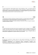
Legenda: A-Griglie passaggio aria B-Allacciamento cavo elettrico C-Aspirazione aria comburente diam. 50mm D-Allacciamento tubo espulsione fumi diam.
Legenda: A-Griglie passaggio aria B-Allacciamento cavo elettrico C-Aspirazione aria comburente diam. 50mm D-Allacciamento tubo espulsione fumi diam.
Apertura - Chiusura porta fuoco Stufa a pellet ENERGY Per aprire la porta inserire la maniglia in dotazione e ruotare in senso orario Maniglia apertura-chiusura porta fuoco ; - Apertura : senso orario - Chiusura : senso antiorario 1.5 Combustibile e uso consentito Le stufe a pellet funzionano esclusivamente con pellet (pastiglie) di varie essenze di legno conformi alla normativa DIN plus 51731 o UNI CEN/TS 14961 o Ö-Norm M 7135 ovvero aventi le seguenti caratteristiche : -Potere calorico min 4.
1.
2 TRASPORTO ED INSTALLAZIONE 2.1 Imballo, movimentazione, spedizione e trasporto Il sollevamento della stufa completa di imballo può essere effettuato mediante carrello elevatore, inserendo le forche, di adeguata lunghezza, nelle apposite sedi del bancale in legno. E’ necessario accertarsi che i dispositivi utilizzati per il sollevamento e il trasporto siano in grado di sopportare il peso della stufa indicato sulla targhetta di identificazione e sul presente manuale.
Ogni installazione deve prevedere uno spazio tecnico di manovra di facile accesso per le manutenzioni periodiche . La stufa è fornita di 4 piedini regolabili per facilitare il posizionamento in presenza di pavimenti non perfettamente planari : per regolare l’altezza inclinare leggermente la stufa e ruotare il piedino interessato al livellamento .
tra apparecchio e camino per l’evacuazione dei prodotti della combustione.
2.7 Schema elettrico 2.8 Pronto intervento Per ogni evenienza è consigliabile disporre di idonei dispositivi antincendio . Se si manifesta un incendio procedere come segue : - Scollegare immediatamente la presa di corrente . - Spegnere tramite l’uso di idonei estintori . - Richiedere l’immediato intervento dei vigili del fuoco . - Non spegnere il fuoco con l’uso di getti d’acqua . 3 SICUREZZE DELLA STUFA 3.
3.3 Sicurezza sovrapressione in camera di combustione Eventuali e/o improvvise sovrapressioni dei fumi di combustione all’interno della camera e dei condotti di evacuazione dei fumi vengono scaricati attraverso l’apertura delle valvole di sicurezza poste sopra lo scambiatore di calore. Durante il normale funzionamento queste valvole sono chiuse dal proprio peso e dalla depressione della camera e garantiscano la tenuta contro l’eventuale uscita dei fumi.
4 USO DELLA STUFA 4.1 Premessa La stufa a pellet presenta il vantaggio di unire il calore della fiamma del legno, alla comodità della gestione automatica della temperatura con la possibilità di programmare settimanalmente l’accensione e lo spegnimento . E possibile eseguire il collegamento ad un termostato e/o cronotermostato esterno per la rilevazione della temperatura in un punto diverso da quello in cui è collocata la stufa.
Di seguito è riportata la tabella dei comandi e dei relativi messaggi visualizzati in fase di programmazione o impostazione dei parametri operativi : La Figura a fianco descrive il significato dei segnalatori di stato sulla parte sinistra del display . L’attivazione nel display di uno dei segmenti segnala l’attivazione del dispositivo corrispondente secondo l’elenco a fianco .
4.3 Accensione 4.3.
Trascorso un certo tempo , se la temperatura fumi non ha raggiunto il valore minimo ammesso la stufa si pone in stato di allarme . - E’ vietato utilizzare liquidi infiammabili per l’accensione . - In caso di continue mancate accensioni contattare il Centro di Assistenza . 4.4 Fase di lavoro Conclusa in modo positivo la fase di ‘AVVIO’ , la stufa passa alla modalità ‘LAVORO ‘ che rappresenta il normale modo di funzionamento .
Orologio Temperatura ambiente Durante la normale operatività nella modalità lavoro , a intervalli prestabiliti viene attivata la modalità ‘PULIZIA BRACIERE’ per una durata prefissata . Potenza Finestra di dialogo 4.5 Spegnimento Per spegnere la stufa è sufficiente premere sul pulsante ‘P4’ per circa 2 secondi .
Livello 1 Livello 2 Livello 3 Livello 4 Valore 03 – Set crono 01 – abilita crono 01 – abilita crono on / off 01 – crono giorno 02 – start 1 giorno 03 – stop 1 giorno 04 – start 2 giorno 05 – stop 2 giorno on / off ora ora ora ora 01 – crono settim 02 – start 1 giorno 03 – stop 1 giorno 04 – lunedi prog 1 05 – martedi prog 1 06 – mercoledi prog 1 07 – giovedi prog 1 08 – venerdi prog 1 09 – sabato prog 1 10 – domenica prog 1 11 – start prog 2 12 – stop prog 2 13 – lunedi prog 2 14 – martedi prog 2 1
Livello 1 Livello 2 Livello 3 Livello 4 Valore 04 – Scegli lingua 01 - italiano set 02 - francese set 03 - inglese set 04 - tedesco set 05 – Modo stand-by on / off 06 – Cicalino on / off 07 – Carico iniziale set 08 – Stato stufa - 4.6.1Menu 01 – regola ventole Le velocità delle ventole dell’aria è automatica e segue la potenza impostata.
Input Entrando nel sottomenu : PROGRAM SETTIM è possibile abilitare , disabilitare e impostare le funzioni del cronotermostato settimanale . Il programmatore settimanale dispone di 4 programmi indipendenti il cui effetto finale è composto dalla combinazione delle 4 programmazioni . Il programmatore settimanale può essere attivato o disattivato , inoltre , impostando OFF nel campo orari , l’orologio ignora il comando corrispondente .
Entrando nel sottomenu : PROGRAM WEEK-END è possibile abilitare , disabilitare e impostare le funzioni del cronotermostato nel week-end ( fine settimana : sabato – domenica ). Livello di menu Input Attivare la programmazione WEEK-END solamente dopo aver disattivato la programmazione settimanale . Al fine di evitare operazioni di avvio e spegnimento non voluti , attivare un solo programma per volta .
4.7 Telecomando Il telecomando funziona con le impostazioni settate nel pannello di comando e consente l’accensione-spegnimento della stufa , la regolazione della potenza e la temperatura che si desidera avere . Essendo un dispositivo che trasmette tramite un diodo ad infrarosso è necessario il puntamento verso l’unità ricevente inserita nel pannello di comando .
4.
5.2 Pulizia contenitore cenere Direttamente sotto il braciere - porta braciere è collocato il contenitore cenere . Per procedere alla sua pulizia è necessario aprire la porta fuoco ed aspirare con un idoneo aspiratore la cenere presente al suo interno ed eventuali residui di combustione. Dopo la pulizia, è necessario chiudere lo sportello. La pulizia del contenitore cenere può essere eseguita ogni 2-3 giorni in funzione dell’utilizzo della stufa. 5.
6 MANUTENZIONE 6.1 Premessa Gli interventi sui componenti interni della stufa devono essere effettuati da personale qualificato, rivolgendosi al centro assistenza autorizzato più vicino. Prima di ogni intervento accertarsi che sia disinserita la spina dell’alimentazione elettrica e la stufa sia completamente fredda. 6.
6.
6.4 Componenti interni della stufa Legenda : 1-Camera di combustione 2-Supporti dx-sx ENERGY 3-Scambiatore in ghisa 4-Pareti laterali 5-Deviatore superiore vermiculite 6-Parete posteriore vermiculite Vista esplosa della camera di combustione e delle parti collegate rif.
Rappresentazioni esplose di: 1- Gruppo braciere 2- Gruppo estrattore fumi 3- Gruppo coclea 4 Legenda : 1-Braciere 2-Porta braciere 3-Guppo tubo aspirazione aria comburente 4-Resistenza elettrica 5-Guarnizione posteriore portabraciere 6-Guarnizione anteriore gruppo aspirazione 1 6 3 5 2 1 2 Legenda : 4 1-Voluta estrattore fumi 2-Guarnizione termica 3-Motore estrattore fumi 4-Tubo espulsione fumi 2 3 Legenda : 1 8 1-Guarnizione serbatoio - convogliatore 2-Flangia ferma motoriduttore 3-Motoridut
6.5 Componenti elettrici Legenda: 1 -Scheda elettronica 2 -Vacuostato di controllo e sicurezza 3 -Termostato sicurezza 4 -Interruttore ON/OFF con fusibili 5 -Sonda ambiente 6 -Sonda fumi 7 -Debimetro 8 -Ventilatore tangenziale dx 9 -Ventilatore tangenziale sx 10-Ventilatore tangenziale posteriore 11-Pannello di comando mod.
7 RICERCA GUASTI 7.1 Gestione degli allarmi La presenza di un allarme si identifica con l’emissione di un segnale acustico (se attivato) e con un messaggio presente sul pannello di controllo. In caso di allarme spegnere la stufa, risolvere la causa che lo ha provocato e riavviare la stufa secondo la normale procedura illustrata nel presente manuale.
Segnalazione Anomalia Cause possibili Rimedi -La camera di combustione è sporca . -Il condotto fumi è ostruito. -La porta fuoco non è chiusa. -Le valvole antiscoppio sono aperte-inceppate . -Il vacuostato è difettoso . -Verificare la pulizia del condotto fumario e della camera di combustione . -Verificare la chiusura ermetica della porta . -Verificare la chiusura delle valvole antiscoppio . -Altre operazioni di ripristino devono essere condotte da un centro di assistenza .
8 ALLEGATI INFORMAZIONI MARCATURA CE CE MARKING INFORMATION COLA 2012 EN 14785 : 2006 Apparecchi per il riscaldamento domestico a pellet di legno Residential space heating appliance fired by wood pellets Ref.
1 2 3 4 GENERAL INFORMATION 1.1 Introduction 1.2 Using the manual 1.3 Safety rules 1.4 Technical description 1.5 Permissible use and fuel 1.6 Accessories supplied 1.7 Reference standards 1.8 Dataplate 1.9 Stove decommissioning 1.10 Instructions for requesting assistance and replacement parts TRANSPORT AND INSTALLATION 2.1 Packing, handling, shipment and transport 2.2 Place of installation, positioning and fireprevention safety 2.3 Air inlet 2.4 Fume exhaust 2.4.1Types of installation 2.
1 GENERAL INFORMATION 1.1 Introduction Dear Customer, First of all we wish to thank you for the trust placed in us by purchasing one of our products. Please read and carefully follow the advice given in this installation, use and maintenance manual in order make best use of the product. 1.2 Using the manual The Manufacturer reserves the right to make technical or aesthetic changes to the products at any time without notice.
1.4 Technical description The stove works exclusively on pellets, providing healthy and safe heat in the room. The stove's automatic control systems guarantee optimum heat output and complete combustion; there are also safety systems to guarantee safe operation for the stove parts and for the user. When correctly installed, the unit works in any outside climatic conditions, and in any case in critical conditions (strong wind, frost, etc.) the safety systems can cut in, shutting down the stove.
Key: A - Air grilles B - Power cable connection C - Combustion air inlet diam. 50 mm D - Flue pipe connection diam. 80 mm E - Pellet hopper door ENERGY vers.
Key: A - Air grilles B - Power cable connection C - Combustion air inlet diam. 50 mm D - Flue pipe connection diam. 80 mm E - Pellet hopper door ENERGY vers.
Apertura - Chiusura porta fuoco Stufa a pellet ENERGY To open the door, fit the handle supplied and turn it clockwise Fire door opening-closing handle; - Opening: clockwise - Closing: anticlockwise 1.5 Permissible use and fuel The pellet stoves work exclusively on pellets in different types of wood complying with Standard DIN plus 51731 or UNI CEN/TS 14961 or Ö-Norm M 7135 or having the following characteristics: min. 4.8 kWh/kg (4180 kcal/kg) Heat value -Density 680-720 kg/m3 Moisture max.
1.
Open the packing, remove the stove from the pallet and position it in the required place, making sure it complies with that provided for. Set the stove down on the floor carefully without bumping and position it in the required place. Make sure the floor can take the weight of the stove, otherwise consult a specialised technician. Disposal or recycling of the packing must be carried out by the end-user in compliance with the current local regulations. 2.
2.3 Air inlet The stove air inlet pipe or intake is located at the back and is round and 50 mm in diameter.
2.5 Brazier and baffle position check Before lighting the stove make sure the brazier is in the correct position, i.e. fitted in the special slots. Also make sure the top smoke baffle is properly fitted. A wrongly positioned baffle can result in malfunctioning and excessive blackening of the glass. At every stove lighting, check the correct position of the brazier on the brazier holder. 2.
3 STOVE SAFETY 3.1 Safety distance from flammable materials To prevent the risk of fire, stove positioning must respect a minimum distance from flammable materials, according to that given in the technical table of the manual and on the dataplate. Pay attention to the type of floor: for delicate and flammable materials it is advisable to use plates in steel or toughened glass as a support base (see section 2 - Transport and Installation).
4 STOVE USE 4.1 Introduction The pellet stove has the advantage of combining heat from a wood flame with the convenience of automatic management of temperature and the possibility of weekly programming of lighting and shutdown. Connection to an external thermostat and/or chronothermostat is possible for detecting the temperature in a different place from where the stove is installed.
On accessing the menu it is possible to obtain the various types of displays and carry out the available settings depending on the access level.
4.3 Lighting 4.3.1 Check before lighting Before lighting the stove: - make sure you have read and understood that given in the manual; - the hopper must be filled with pellets; - the combustion chamber must be clean; - the brazier must be completely free, cleaned of any combustion residuals and correctly fitted in the brazier holder; - check hermetic closing of the fire door and ash pan; - check the connection of the power cable and switching to ON/1 of the switch located on the back of the stove.
After a certain time has elapsed, if the fume temperature has not reached the minimum permissible value the stove goes in alarm status. - Do not use flammable liquids to light the stove. - In case of persistent failed lighting, contact the Service Centre. 4.4 Work stage After the 'STARTUP' stage, the stove goes to the 'WORK' mode which represents the normal operation mode. The user can adjust the heat output from the max. value of 5 to a min. of 1 with the buttons ‘P5’ and ‘P6’.
Clock Room temperature During normal operation in work mode, the 'CLEANING FIRE POT’ mode is activated at fixed intervals for a set duration. 4.5 Shutting down Dialogue box Output To shut down the stove, just press the button 'P4' for about 2 seconds. The auger is stopped immediately and the fume extractor is brought to high speed, with the message 'FINAL CLEANING' displayed; both fume extraction and air ventilation motors remain on until the stove temperature has lowered sufficiently.
Level 1 Level 2 Level 3 Level 4 Value 03 – Set chrono 01 – enable chrono 01 – enable chrono on / off 01 – day chrono 02 – start 1 day 03 – stop 1 day 04 – start 2 day 05 – stop 2 day on / off time time time time 01 – week chrono 02 – start 1 day 03 – stop 1 day 04 – Monday prog 1 05 – Tuesday prog 1 06 – Wednesday prog 1 07 – Thursday prog 1 08 – Friday prog 1 09 – Saturday prog 1 10 – Sunday prog 1 11 – start prog 2 12 – stop prog 2 13 – Monday prog 2 14 – Tuesday prog 2 15 – Wednesday prog 2 16 –
Level 1 Level 2 Level 3 Level 4 Value 04 – Select language 01 - Italian set 02 - French set 03 - English set 04 - German set 05 – Standby mode on / off 06 – Buzzer on / off 07 – Initial loading set 08 – Stove status - 4.6.1 Menu 01 – adjust fans The speed of the air fans is authomatic and follows the maximum power programmed.
By accessing the submenu: WEEK PROGRAM it is possible to enable/disable and set the weekly chronothermostat functions. The weekly programmer has 4 independent programmes whose final effect consists of a combination of the 4 programmings. The weekly programmer can be activated/deactivated; also, by setting OFF in the times field, the clock ignores the corresponding command. Carry out programming making sure not to overlap the hours of activation and/or deactivation on the same day in different programmes.
By accessing the submenu: WEEK-END PROGRAM it is possible to enable/disable and set the week-end (Saturday Sunday) chronothermostat functions. Input Menu level Activate WEEK-END programming only after deactivating the weekly programming. In order to avoid unwanted start and shutdown operations, activate only one programme at a time. Deactivate the daily programme if the weekly programme is required; with this setting it is advisable to deactivate the week-end programme. 4.6.
4.7 Remote control The remote control works with the settings made in the control panel and allows stove lighting-shutdown, and adjustment of the required output and temperature. Since this device transmits through an infrared diode, it must be pointed at the receiver unit in the control panel.
4.9 Idle period (end of season) If the stove is not used for long periods, and/or at the end of each season, it is advisable to proceed as follows - remove all the pellets from the hopper; - disconnect the power and remove the power cable; - clean thoroughly and, if necessary, have any damaged parts replaced by qualified personnel; - protect the stove from dust with suitable covering; - store in a dry and safe place protected from atmospheric agents.
5.2 Cleaning the ash container The ash container is located directly under the brazier - brazier holder. To clean it, open the fire door and remove the ash and any combustion residuals using a suitable vacuum cleaner. The door must be closed after cleaning. The ash container can be cleaned every 2-3 days depending on stove use. 5.3 Cleaning the glass and air slots The glass can be cleaned using a damp cloth and specific non-abrasive detergents.
6 MAINTENANCE 6.1 Introduction Operations on the internal parts of the stove must be carried out by qualified personnel. Contact the nearest authorised service centre. Make sure the stove is unplugged and cold before carrying out any work on it. 6.2 Removing the cladding ENERGY vers.
6.3 Removing the cladding ENERGY vers.
6.
Exploded views of: 1 - Brazier assembly 2 - Fume extractor assembly 3 - Auger assembly 4 Key: 1 - Brazier 2 - Brazier holder 3 - Combustion air inlet pipe assembly 4 - Electrical element 5 - Brazier holder rear seal 6 - Suction unit front seal 1 6 3 5 2 1 2 Key: 4 1 - Fume extractor volute 2 - Thermal seal 3 - Fume extractor motor 4 - Fume exhaust pipe 2 3 Key: 1 8 1 - Conveyor - hopper seal 2 - Gearmotor support flange 3 - Gearmotor 4 - Auger 5 - Seal for chute 6 - Pellet chute 7 - Conveyor-
6.
7 TROUBLESHOOTING 7.1 Alarm management Alarms are indicated by an acoustic signal (if activated) and a message on the control panel. In case of an alarm, shut down the stove, eliminate the cause and restart the stove according to the normal procedure described in this manual. The alarms, with causes and cures, which can appear on the control panel are listed below: ALARMS - MESSAGES Signalling Fault Possible causes Cures -The stove does not start. -No power during the lighting stage.
Signalling AL 8 NO NEG PRESS AL 9 INSUFF DRAUGHT AL b AUG TRIAC ERROR WAITING COOL AIR FLOW METER FAILURE SERVICE DUE Fault Possible causes Cures -The combustion chamber is dirty. -The fume duct is obstructed. -The fire door is not closed. -The overpressure valves are open-stuck. -Faulty vacuum switch. -Check cleanness of the fume duct and combustion chamber. -Check hermetic closing of the door. -Check closing of the overpressure valves.
8 ENCLOSURES CE MARKING INFORMATION COLA 2012 EN 14785 : 2006 Wood pellet-burning domestic heating appliances Ref. ENERGY vers.steel - glass Min. safety distance from flammable materials rear - right/left side - floor 200 – 300 – 0 mm CO emissions at 13% O2 in fumes Nom. Output : 0.01 % Red. output : 0.01 % Dust emissions at 13% O2 in fumes Nom. output : 8 mg/m Max. water operating pressure : Flue gas temperature : Nom. output 202.5 °C Red. output 86.
1. RECOMMANDATIONS GÉNÉRALES 1.1. Introduction 1.2. Comment utiliser ce manuel 1.3. Règles de sécurité 1.4. Description technique 1.5. Combustible et usage prévu 1.6. Accessoires fournis 1.7. Normes de référence 1.8. Plaque d’identification 1.9. Mise hors service du poêle 1.10. Demande d’intervention et de pièces détachées 2. TRANSPORT ET INSTALLATION 2.1. Emballage,manutention,expédition et transport 2.2. Lieu d'installation, mise en place et sécurité anti-incendie 2.3. Prise d'air 2.4.
1 RECOMMANDATIONS GÉNÉRALES 1.1 Introduction Cher Client ! Nous vous remercions de la confiance que vous nous avez accordée en achetant ce produit. Nous vous invitons à lire et à suivre attentivement les conseils fournis par ce manuel d’installation, d'utilisation et d'entretien pour exploiter au mieux les qualités de cet appareil. 1.2 Comment utiliser ce manuel La société COLA s.r.l. se réserve d'apporter des modifications techniques ou esthétiques à ses produits à n'importe quel moment et sans préavis.
1.4 Description technique Le poêle fonctionne exclusivement à granulés et propage une chaleur saine et rassurante dans la pièce. Les systèmes de contrôle automatiques dont il est pourvu assurent un rendement thermique optimal et une combustion complète. Des systèmes de sécurité garantissent des conditions de sécurité pour l'utilisateur et la fiabilité des composants du poêle.
Légende : A - Grilles de passage d'air B - Connexion du câble électrique C - Aspiration d'air comburant diam. 50 mm D - Raccordement tuyau d'évacuation des fumées, diam.
Dimensions du poêle à granulés ENERGY verre Légende : A - Grilles de passage d'air B - Connexion du câble électrique C - Aspiration d'air comburant diam. 50 mm D - Raccordement tuyau d'évacuation des fumées, diam.
Pour ouvrir la porte insérer la poignée fournie et tourner en sens horaire Poignée d'ouverture-fermeture porte de foyer ; - Ouverture : sens horaire - Fermeture : sens anti-horaire 1.
1.
2 TRANSPORT ET INSTALLATION 2.1 Emballage, manutention, expédition et transport Le poêle peut être soulevé à l'aide d'un chariot élévateur en introduisant les fourches d'une longueur adéquate aux endroits prévus à cet effet sur la palette en bois. S'assurer que la capacité des appareils utilisés pour le levage et le transport est suffisante pour supporter le poids du poêle indiqué sur la plaque d'identification et dans ce manuel.
Le poêle est doté de 4 pieds réglables pour faciliter sa mise en place sur des sols irréguliers. Pour régler la hauteur du pied, incliner le poêle et tourner le pied jusqu'à obtenir la juste hauteur. Le poêle est fourni avec une sonde d’ambiance fixée par un collier sur la paroi arrière du poêle. Nous conseillons son déplacement afin d’améliorer lecture de la température ambiante. La longueur du câble de la sonde, permet de la déplacer et de la positionner plus haut.
CARNEAU ou CONDUIT DE RACCORDEMENT : conduit ou élément de raccordement entre l'appareil et le conduit de fumée, pour l'évacuation des produits de combustion.
2.7 Schéma électrique ALT=Thermostat de securitè ALD=Débimètre 2.8 Première intervention Il est toujours conseillé d'installer des équipements anti-incendie appropriés. En cas d'incendie : - Débrancher immédiatement le câble d'alimentation du poêle. - Éteindre le feu avec des extincteurs conformes à la réglementation en vigueur. - Appeler immédiatement les sapeurs-pompiers. - Ne pas utiliser de jets d'eau pour éteindre le feu. 3 SÉCURITÉ 3.
3.3 Sécurité en cas de surpression dans la chambre de combustion En cas de surpression inattendue des fumées de combustion à l’intérieur de la chambre et des conduits d'évacuation, les fumées seront évacuées à travers des soupapes de sûreté installées au-dessus de l'échangeur de chaleur. Durant le fonctionnement normal, ces soupapes restent fermées sous leur propre poids et sous l'effet de la dépression de la chambre de combustion de sorte à garantir l'étanchéité contre l’évacuation éventuelle des fumées.
4 UTILISATION DU POÊLE 4.1 Introduction Le poêle à granulés offre l'avantage de combiner la chaleur de la flamme du bois et la commodité de la gestion automatique de la température, avec la possibilité de programmer hebdomadairement l'allumage et d'extinction. Il est possible d'effectuer le branchement à un thermostat et/ou chronothermostat externe pour mesurer la température en un endroit différent de celui d’installation du poêle.
Pour accéder au menu : - appuyer sur la touche CONSIGNE (SET) ‘P3’ ; - appuyer plusieurs fois sur les touches ‘P5’ ,‘P6’ pour dérouler les menus ; - appuyer sur une des touches d'augmentation/diminution ‘P1’, ‘P2’, pour ajuster le paramètre désiré ; - appuyer sur la touche CONSIGNE (SET) ‘P3’ pour confirmer la valeur du paramètre.
4.3 Allumage 4.3.
Passé un certain temps, si la température des fumées atteint la valeur min. admissible, le poêle se mettra en position d'alarme. - Il est interdit d'utiliser des liquides inflammables pour l'allumage du poêle. - En cas d'allumages manqués répétés, faire appel au SAV. 4.4 Fonctionnement Après la phase de démarrage réussie, le poêle passe en mode ‘FONCTIONNEMENT‘ qui représente le régime normal. L'utilisateur peut alors régler la puissance de chauffe par les boutons ‘P6’ et ‘P5’, de la valeur max.
Horloge Température ambiante Pendant le fonctionnement normal, à intervalles prédéfinis, la modalité ‘NETTOYAGE BRASIER’ pour une durée prédéfinie est activée. Fenêtre de dialogue Puissan prérégléece 4.5 Extinction Pour arrêter le fonctionnement du poêle, il suffit d'appuyer sur le bouton ‘P4’ pendant 2 secondes environ. La vis sans fin est immédiatement arrêtée et le fonctionnement de l'extracteur des fumées est amené à une vitesse élevée.
Niveau 1 Niveau 2 Niveau 3 Niveau 4 Valeur 03 – réglage du chrono 01 – activation du chrono 01 – activation du chrono on / off 01 – chrono jour on / off 02 – program jour 02 – start 1 jour heure 03 – stop 1 jour heure 04 – start 2 jour heure 05 – stop 2 jour heure 01 – chrono semaine on / off 03 – program semaine 02 – start 1 jour heure 03 – stop 1 jour heure 04 – lundi prog 1 on / off 05 – mardi prog 1 on / off 06 – mercredi prog 1 on / off 07 – jeudi prog 1 on / off 08 – ven
Niveau 1 Niveau 2 Niveau 3 Niveau 4 Valeur 04 – choix de la langue 01 - italien set 02 - français set 03 - anglais set 04 - allemand set 05 – mode veille (stand-by) on / off 06 – alarme sonore (buzzer) on / off 07 – chargement initial set 08- État du poêle - 4.6.1 Menu 01 – réglage des ventilateurs La vitesse des ventilateurs air est automatiquement asservie à la puissance réglée.
Entrée Aller dans le sous-menu : PROGRAM SEMAINE, pour activer, désactiver et présélectionner les fonctions du chronothermostat hebdomadaire. Le programmateur hebdomadaire dispose de 4 programmes indépendants qui en final se traduisent par la combinaison des 4 programmations. Le programmateur hebdomadaire peut être activé ou désactivé et, d'autre, part, en mettant OFF dans le champ horaires, l'horloge ignorera la commande correspondante. La programmation doit se faire avec grande attention.
Aller dans le sous-menu : PROGRAM WEEK-END, pour activer, désactiver et présélectionner les fonctions du chronothermostat dans le week-end ( fin de semaine : samedi – dimanche ). Niveau de menu Activer la programmation WEEK-END uniquement après avoir désactivé la programmation hebdomadaire. Pour éviter des mises en marche et des extinctions du poêle non désirées, activer un seul programme à la fois.
4.7 Télécommande La télécommande fonctionne avec les présélections ou préréglages du tableau de commande et permet l'allumage et l'extinction du poêle, ainsi que la régulation de la puissance et de la température désirée. La télécommande transmet par une diode infrarouge et doit donc être dirigée vers le récepteur situé sur le tableau de commande du poêle.
4.
5.2 Nettoyage du cendrier Le cendrier amovible est situé directement sous l'ensemble brasier et support de brasier. Pour le nettoyage, ouvrir la porte de foyer et aspirer la cendre et tout autre résidu de combustion avec un aspirateur approprié. À la fin du nettoyage, fermer la porte. Le décendrage doit se faire tous les 2-3 jours en fonction de l’utilisation du poêle. 5.3 Nettoyage de la vitre et des fentes d'aération Nettoyer la vitre à l'aide d'un chiffon humide et d'un détergent non abrasif.
6 ENTRETIEN 6.1 Introduction Les interventions sur les composants du poêle doivent être effectuées par un professionnel qualifié, en s'adressant au centre d'assistance le plus proche. Avant toute intervention, s'assurer d'avoir débranché le cordon d'alimentation électrique et que le poêle est froid. 6.
6.
6.4 Composants internes du poêle Légende : 1 - Chambre de combustion 2 - Supports droit et gauche ENERGY 3 - Échangeur en fonte 4 - Parois latérales vermiculite 5 - Déflecteur supérieur vermiculite 6 - Paroi postérieure vermiculite Éclaté de la chambre de combustion et des parties reliées réf.
Éclatés de : 1 - Groupe brasier 2 - Groupe extracteur des fumées 3 - Groupe vis sans fin 4 Légende : 1 - Brasier 2 - Support de brasier 3 - Tuyau d'aspiration d'air comburant 4 - Résistance électrique 5 - Joint arrière de support de brasier 6 - Joint avant du groupe aspiration 1 6 3 5 2 1 2 Légende : 4 1 - Volute extracteur de fumées 2 - Joint thermique 3 - Moteur d'extracteur de fumées 4 - Tuyau d'évacuation des fumées 2 3 Légende : 1 8 1 - Joint de réservoir-convoyeur 2 - Flasque d'arrêt mo
6.5 Composants électriques Légende : 1 - Carte électronique 2 - Vacuostat de contrôle et sécurité 3 - Thermostat de sécurité 4 - Interrupteur ON-OFF avec fusibles 5 - Sonde de température ambiante 6 - Sonde de température des fumées 7 - Débitmètre 8 - Ventilateur tangentiel droit 9 - Ventilateur tangentiel gauche 10 - Ventilateur tangentiel postérieur 11 - Tableau de commande mod.
7 RECHERCHE DES PANNES 7.1 Gestion des alarmes Les alarmes sont signalées à la fois visuellement à l'écran (message) et par un signal sonore (si activé). En cas d'alarme, éteindre le poêle, éliminer la cause de la panne et remettre en marche le poêle en respectant la procédure normale décrite dans ce manuel. Les alarmes visualisées sur le tableau de commande sont les suivantes : ALARMES - MESSAGES Signalisation Anomalie Causes probables Solutions -Le poêle ne s'allume pas.
Signalisation AL 8 ABSENCE DÉPRESS Anomalie -En marche, le poêle relève une pression inférieure au seuil de tarage du vacuostat. -Le système est arrêté. Causes probables Solutions -La chambre de combustion est encrassée. -Le conduit de fumée est obstrué. -La porte de foyer n'est pas fermée. -Les clapets anti-explosion sont ouverts-coincés. -Le vacuostat est défectueux. -Vérifier l'état de propreté du conduit de fumée et de la chambre de combustion. -Vérifier la fermeture hermétique de la porte.
8 ANNEXES INFORMATIONS RELATIVES AU MARQUAGE CE COLA 2012 EN 14785 : 2006 Appareils de chauffage domestique à granulés de bois Réf. ENERGY acier - verre Distance minimale de sécurité par rapport aux matériaux inflammables À l'arrière, sur les côtés droit et gauche, au sol 200 – 300 – 0 mm Émissions de CO à 13% O2 dans les produits de combustion P. nom. : 0,01% P. réd. : 0,01% Émissions de poussières à 13% O2 dans les produits de combustion P. nom. : 8 mg/m Pression max.
1 2 3 4 ALLGEMEINE HINWEISE 1.1 Vorwort 1.2 Nachschlagen im Handbuch 1.3 Sicherheitsvorschriften 1.4 Technische Beschreibung 1.5 Brennstoff und zulässiger Gebrauch 1.6 Zubehör 1.7 Bezugsnormen 1.8 Typenschild 1.9 Außerbetriebsetzung des Ofens 1.10 Anleitungen für die Anforderung von Kundendiensteingriffen und Ersatzteilbestellungen TRANSPORT UND INSTALLATION 2.1 Verpackung, Handhabung, Versand und Transport 2.2 Aufstellungsort, Aufstellung und Brandschutz 2.3 Lufteinlass 2.4 Abgasführung 2.4.
1 ALLGEMEINE HINWEISE 1.1 Vorwort Verehrter Kunde, Wir danken Ihnen für das Vertrauen, das Sie uns mit dem Kauf dieses Geräts entgegengebracht haben. Bitte lesen und befolgen Sie diese Installations-, Gebrauchs- und Wartungsanleitung, um die Produkteigenschaften optimal nutzen zu können. 1.2 Nachschlagen im Handbuch Der Hersteller behält sich vor, die technischen Merkmale und das Design der Produkte jederzeit und ohne Vorankündigung zu ändern.
1.4 Technische Beschreibung Der Pelletofen darf ausschließlich mit Pellets beschickt werden und verbreitet eine gesunde, sichere Wärme im Raum. Seine automatischen Regelsysteme sorgen für eine optimale Wärmeleistung und eine vollständige Verbrennung. Die vorhandenen Sicherheitssysteme gewährleisten einen für die Ofenkomponenten und den Benutzer sicheren Betrieb.
Zeichenerklärung: A - Luftgitter B - Netzkabelanschluss C - Verbrennungsluftansaugung Durchm. 50 mm D - Anschluss Rauchabzugsrohr Durchm. 80 mm E - Tür des Pelletsbehälters Abmessungen Pelletofen ENERGY ausf.
Zeichenerklärung: A - Luftgitter B - Netzkabelanschluss C - Verbrennungsluftansaugung Durchm. 50 mm D - Anschluss Rauchabzugsrohr Durchm. 80 mm E - Tür des Pelletsbehälters 102 Abmessungen Pelletofen ENERGY ausf.
Um die Tür zu öffnen, den mitgelieferten Griff einsetzen und Gegen den Uhrzeigersinn Griff zum Öffnen/Schließen der Feuerraumtür; - Schließen: Gegen den Uhrzeigersinn - Öffnen: Im Uhrzeigersinn 1.5 Brennstoff und zulässiger Gebrauch Die Pelletöfen funktionieren ausschließlich mit Pellets (Presslingen) aus verschiedenen Holzarten, die die Vorschriften der Normen DIN Plus 51731 oder UNI CEN/TS 14961 oder Ö-Norm M 7135 erfüllen, bzw.
1.
2 TRANSPORT UND INSTALLATION 2.1 Verpackung, Handhabung, Versand und Transport Der Ofen kann mit einem Gabelstapler angehoben werden, indem die ausreichend langen Gabeln an den passenden Stellen in der Holzpalette eingeführt werden. Es muss unbedingt sichergestellt werden, dass die Hebeund Transportmittel für das am Typenschild und im vorliegenden Handbuch angegebene Maschinengewicht geeignet sind. Auf keinen Fall die Last in Bereichen befördern, in denen das Herunterfallen eine Gefahr darstellen könnte.
Bei der Installation muss genügend Freiraum gelassen werden, damit das Gerät für die regelmäßig anfallenden Wartungseingriffe problemlos zugänglich ist. Der Ofen wird mit 4 verstellbaren Füßen geliefert, um die Aufstellung auf nicht perfekt ebenen Fußböden zu erleichtern: Um die Höhe eines Stellfußes zu verstellen, den Ofen etwas neigen und den betreffenden Stellfuß drehen.
ABGASKANAL oder RAUCHROHR: Leitung oder Verbindungsstück zwischen Feuerstätte und Schornstein für die Abführung der Verbrennungsprodukte. Technische Anforderungen an den ABGASKANAL: - Der Abgaskanal darf keine Räume durchqueren, in denen die Installation von Heizgeräten verboten ist; - die Verwendung von Metallschläuchen oder Rohren aus Asbestzement ist verboten; - die Verwendung von Elementen mit Gegenneigung ist verboten; - in den waagerechten Abschnitten darf der Kanalverlauf max.
2.7 Elektroschaltplan ALF = Haupt-Sicherheitsthermostat ALC = Unterdruckmesser 2.8 Notfallmaßnahmen Auf jeden Fall sind geeignete Brandbekämpfungsmittel bereit zu stellen. Im Brandfall folgendermaßen vorgehen: - Stromzufuhr sofort trennen. - Mit geeigneten Feuerlöschern löschen; - Sofort die Feuerwehr rufen. - Nicht mit Wasser löschen. 3 SICHERHEITSRELEVANTE HINWEISE UND VORRICHTUNGEN 3.
3.3 Überdruckventil in der Verbrennungskammer Eventuelle und/oder plötzliche Überdrücke der Verbrennungsgase in der Kammer und in den Rauchabzugsleitungen werden durch das Öffnen der Sicherheitsventile, die sich am vorderen Teil der Brennkammer befinden, abgelassen. Während des normalen Betriebs sind diese Ventile durch das eigene Gewicht und den Unterdruck der Kammer geschlossen und verhindern dadurch einen eventuellen Rauchaustritt.
4 GEBRAUCH DES OFENS 4.1 Vorwort Der Pelletofen vereint die wohlige Wärme von Holzfeuer mit der bequemen automatischen Temperaturregelung und der Möglichkeit, die Ein-und der Ausschaltung für die ganze Woche zu programmieren. Der Ofen kann an einen externen Thermostat und/oder Uhrenthermostat angeschlossen werden, um die Temperatur fern vom Aufstellungsort des Ofens zu messen.
Nach Öffnen des Menüs können die verschiedenen Anzeigearten eingerichtet und die je nach Zugriffsebene verfügbaren Einstellungen vorgenommen werden.
4.3 Einschalten 4.3.1 Kontrolle vor Inbetriebnahme Vor dem Einschalten des Ofens müssen folgende Kontrollen durchgeführt werden: - Die Betriebsanleitung muss gelesen und verstanden worden sein. - Der Behälter muss mit Pellets gefüllt sein. - Die Brennkammer muss sauber sein. - Der Brenntopf muss sauber, vollständig frei von eventuellen Verbrennungsrückständen und korrekt im Brenntopfhalter positioniert sein. - Feuerraumtür und Aschekasten müssen dicht verschlossen sein.
Wenn die Abgastemperatur nach Ablauf einer bestimmten Zeit nicht den zulässigen Mindestwert erreicht hat, schaltet der Ofen auf Alarmzustand. - Der Ofen darf nicht mit entzündlichen Flüssigkeiten angezündet werden. - Sollten wiederholt Probleme beim Anzünden auftreten, kontaktieren Sie bitte den Kundendienst. 4.4 Betriebsphase Nach erfolgreichem Abschluss des ‘ZÜNDVORGANGS’ wechselt der Ofen auf den normalen Betriebszustand ‘BETRIEB‘.
Raumtemperatur Uhr Während des normalen Betriebs wird in bestimmten vorgegebenen Zeitabständen die Betriebsart ‘BRENNTOPFREINIGUNG’ aktiviert, deren Dauer ebenfalls vorgegeben ist. Leistung Dialogfenster 4.5 Ausschalten Zum Ausschalten des Ofens einfach die Taste ‘P4’ etwa 2 Sekunden lang drücken. Die Förderschnecke wird sofort angehalten, das Saugzuggebläse schaltet auf eine hohe Drehzahl und auf dem Display erscheint die Meldung ‘ENDREINIGUNG’; beide Motoren, d.h.
Ebene 1 Ebene 2 Ebene 3 Ebene 4 Wert 03 – Uhrenthermostat einstellen 01 – Uhrenthermostat aktivieren 01 – Uhrenthermostat aktivieren on / off 01 – Uhrenthermostat Tag on / off 02 – Start 1 Tag Uhrzeit 02 – Program Tag 03 – Stop 1 Tag Uhrzeit 04 – Start 2 Tag Uhrzeit 05 – Stop 2 Tag Uhrzeit 01 – Uhrenthermostat Woche on / off 02 – Start 1 Tag Uhrzeit 03 – Program Woche 03 – Stop 1 Tag Uhrzeit 04 – Montag Prog 1 on / off 05 – Dienstag Prog 1 on / off 06 – Mittwoch Prog 1 on / off
Ebene 1 Ebene 2 Ebene 3 Ebene 4 Wert 04 – Sprache wählen 01 - Italienisch Set 02 - Französisch Set 03 - Englisch Set 04 - Deutsch Set 05 – Standbybetrieb on / off 06 – Summer on / off 07 – Erste Pelletfüllung Set 08 – Betriebszustand des Ofens - 4.6.1 Menü 01 – Lüfter regeln Die Drehzahl der Lüfterräder ist automatisch und hängt von der eingestellten Leistung ab. Wenn der Zustrom von Warmluft eingeschränkt werden soll, kann die max.
Input Bei Öffnen des Untermenüs: PROGRAM WOCHE können die wöchentlich programmierten Funktionen des Uhrenthermostats aktiviert, deaktiviert und eingestellt werden. Das Wochenprogramm verfügt über 4 unabhängige Programme, deren Endeffekt aus der Kombination der 4 Programmierungen besteht. Das Wochenprogramm kann aktiviert oder deaktiviert werden. Durch Eingabe von OFF in das Feld mit den Stunden wird der entsprechende Befehl ignoriert.
Bei Öffnen des Untermenüs: PROGRAM WOCHENENDE können die Funktionen des Uhrenthermostats am Wochenende aktiviert, deaktiviert und eingestellt werden (Wochenende: Samstag – Sonntag). Menüebene Die Programmierung WOCHENENDE nur nach Deaktivierung der Wochenprogrammierung aktivieren. Um ein unbeabsichtigtes Ein- und Abschalten zu vermeiden, jeweils immer nur ein Programm aktivieren.
4.7 Fernbedienung Die Fernbedienung funktioniert mit den am Bedienpanel vorgenommenen Einstellungen und dient zum Ein/Ausschalten des Ofens sowie zur Regelung der Leistung und der gewünschten Temperatur. Da sie an eine Infrarotdiode sendet, muss sie zum Empfänger im Bedienpanel gerichtet werden.
4.9 Außerbetriebnahme Wird der Ofen für längere Zeit nicht benutzt, folgendermaßen vorgehen - Den Pelletbehälter vollständig ausleeren. - Die Stromzufuhr trennen und das Kabel vom Schalter entfernen; - Gründlich säubern und bei Bedarf alle beschädigten Teile von Fachpersonal ersetzen lassen. - Den Ofen abdecken, um ihn vor Staub zu schützen. - An einem trockenen, witterungsgeschützten Ort unterstellen.
5.2 Reinigung des Aschenbehälters Direkt unter dem Brenntopf/dem Brenntopfhalter befindet sich ein herausnehmbarer Aschebehälter. Per procedere alla sua pulizia è necessario aprire la porta fuoco ed aspirare con un idoneo aspiratore la cenere presente al suo interno ed eventuali residui di combustione. Nach der Reinigung muss die Tür geschlossen werden, Die Reinigung des Aschebehälters muss je nach Ofengebrauch alle 2-3 Tage durchgeführt werden. 5.
6 WARTUNG 6.1 Vorwort Die Eingriffe an Innenkomponenten des Ofens müssen von autorisiertem Fachpersonal durchgeführt werden wenden Sie sich hierfür bitte an den nächstgelegenen Kundenservice. Vor jedem Eingriff am Ofen muss sichergestellt werden, dass der Netzstecker gezogen und der Ofen kalt ist. 6.2 Ausbau der ENERGY ausf.
6.3 Ausbau der ENERGY ausf.
6.4 Innere Ofenkomponenten Zeichenerklärung: 1 - Brennkammer 2 - Halterungen re./li.
Explosionszeichnungen von: 1 - Baugruppe Brenntopf 2 - Baugruppe Saugzuggebläse 3 - Baugruppe Förderschnecke 4 Zeichenerklärung: 1 - Brennschale 2 - Brennschalenhalter 3 - Baugruppe Verbrennungsluft-Ansaugrohr 4 - Elektr.
6.5 Elektrische Bauteile Zeichenerklärung: 1 - Elektronikplatine 2 - Kontroll- und Sicherheits-Unterdruckwächter 3 - Sicherheitsthermostat 4 - EIN/AUS-Schalter mit Schmelzsicherungen 5 - Serielle Schnittstelle 6 - Raumtemperaturfühler 7 - Abgasfühler 8 - Rechter Tangentialventilator 9 - Linker Tangentialventilator 10 - Hinterer Tangentialventilator 11 - Bedienpanel Mod.
7 FEHLERSUCHE 7.1 Verwaltung der Alarmmeldungen Ein Alarm wird durch ein akustisches Signal (sofern aktiviert) und eine Meldung am Bedienpanel angezeigt Bei Auftreten eines Alarms den Ofen abschalten, Alarmursache beheben und erst dann den Ofen wie im vorliegenden Handbuch beschrieben wieder einschalten.
Anzeige Betriebsstörung Mögliche Ursachen Abhilfen - Die Brennkammer ist verschmutzt. - Das Rauchabzugsrohr ist verstopft. - Die Feuerraumtür ist nicht geschlossen. - Die Berstschutzventile sind offen/verklemmt. - Der Unterdruckwächter ist defekt. - Kontrollieren, ob Rauchabzugsrohr und Brennkammer sauber sind. - Kontrollieren, ob die Tür dicht verschlossen ist. - Kontrollieren, ob die Berstschutzventile geschlossen sind.
8 ANLAGEN Informationen zur CE-Kennzeichnung COLA 2012 EN 14785 : 2006 Pelletöfen für den Heimbetrieb Raumheizer zur Verfeuerung von Holzpellets Nr. ENERGY sthal - glas Mindestsicherheitsabstand von entflammbaren Materialien 200 – 300 – 0 mm CO-Emission bei 13% O2 in den Verbrennungsprodukten Pnom : 0.01 % Prid : 0.01 % Staubemission bei 13% O2 in den Verbrennungsprodukten Pnom : 8 mg/m Max. Betriebswasserdruck : - bar Abgastemperatur : P nom 202.5 °C Pred 86.