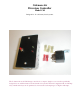
Coleman Air Diversion Controller Model C40 Designed for 12 volt battery based systems. The Coleman Air model C40 charge controller is a compact, simple to use controller specifically designed for use with moderate wind and small solar systems. The unit is supplied with one 40 Amp relay. Additional relays can be purchased to increase the total amperage to as high as 160 amps.
Introduction This diversion controller is the result of our many attempts to use the controllers currently on the market (offered by some of the largest names in the business), to work in conjunction with our wind turbines. None of these diversion controllers did what we needed a diversion controller to do. So we designed our own -- and added all of the features that are truly needed in a diversion controller.
There is nothing stopping you from adding more relays to increase the total load capability. The following precautions must be taken into account if you wish to add more relays. The internal regulator can handle 4 relays (40 amp automotive type). About load diversion. The basic operating philosophy of a diversion controller is quite simple.
Diversion Load Types: A diversion load needs to be larger (by at least 20%), than the sum total of all your solar/wind/hydro charge sources combined. When the diversion load is too small, battery voltage may continue to rise, even when the dump is active. It is also important to use a load that is not likely to fail. Light bulbs and similar such loads are not good diversion (dummy) loads, since they will fail and you may be left with no method to dump the excess energy from your batteries.
Step 1: Remove the two screws that are holding the faceplate of the controller onto the switch box and carefully remove the controller from the box. Set the controller electronics aside. Mount the box as desired, indoors and out of high moisture areas. Punch out one of the openings in the switch box (bottom side normally.) Take a look at the bottom of the relay and you will notice some numbering. This is the numbering referenced in the hookup drawings that follow: Mount the relay next to the controller.
Calibrating the Diversion Controller. The factory using the following settings has already calibrated this controller. The Green LED will be illuminated as follows 1 - (One) Flash indicates the battery is low -- less than 12 volts. 2 - (Two) Flashes indicates the battery is 12 to 12.3V 3 - (Three) Flashes indicates the battery is 12.4 to 12.7v (A fully charged lead acid battery at rest) 4 - (Four) Flashes indicate the battery is 12.8 to 13.0V 5 - (Five) Flashes indicates the battery is above 13.
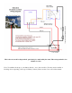
This is the most used hookup method, particularly for wind and hydro units. This wiring method is also suitable for solar. Note: Your turbine hooks up to your battery directly – not to the controller. (You may need a rectifier or blocking diode, depending on the type of turbine you have). Please see the notes at end of the manual.
This wiring is for solar systems. In this mode, the charge source is disconnected from the batteries and no diversion load is used. This wiring method is not suitable for wind/hydro units since they need to remain under a load during normal operation to prevent over-speed.
This wiring method is similar to the standard diversion control wiring, except that when the trip point is reached, power from the charge source (wind/solar etc) is no longer allowed to reach the batteries, but instead is sent directly to the diversion load. Use this method if you want your turbine to see a larger load when the batteries are full, possibly causing a slow down in your turbine RPM. Please see the notes about diversion philosophy in the earlier portions of this manual.
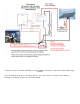
Perfect if you have both Solar and Wind (or Solar and Hydro), and want to control both of them with a single controller. Note: Your turbine hooks up to your battery directly – not to the controller. (You may need a rectifier or blocking diode). Please see the note at end of the manual.
Parts list for Coleman Air - Diversion Controller v 1.0 (1) PCB Circuit Board assembled, tested and calibrated, mounted onto a solid steal faceplate. (1) Single gang switchbox (standard outlet box.) (1) 12V – 40A Relay. (2) Red spade connectors. (3) Yellow spade connectors. Please note: this controller does not include a blocking diode or an A/C to D/C rectifier, as these are specific to your application.