
Instructions / Assembly


English - 11
Suggested Cleaning Materials:
•Milddishwashingliquiddetergent•Hotwater
•Wirebrush•Paperclip•Nyloncleaningpad
•Softbrass-bristledbrush•Puttyknife•Scraper
Component Cleaning:
• BURNER: Wire-brush loose corrosion from the burner
exterior. Clean clogged gas port holes with an opened
paper clip. Replace corroded or damaged burner that
would emit excess gas.
• COOKING GRATE: Clean cooking grates with mild soap
and hot water. Remove stubborn residue with a mild
cleanser or scrub brush. DO NOT use a commercial oven
cleaner.
• GRILL INTERIOR: Remove grates. Scrape side with tools
and remove excess grease and cooking residue.
Fig. 38
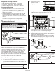
Cleaning the Venturi
Spider’s nests or wasp’s mud inside the venturi may
cause re at the valve. If a re occurs, immediately turn
off the gas supply at the control valve (see representative
illustration in Fig. 37).
WARNING
REPRESENTATIVE ILLUSTRATION
Fig. 37
REPRESENTATIVE ILLUSTRATION
Fig. 42
Note:
Spiders and small insects can spin webs and build nests
inside the venturi tubes. This especially occurs in late
summer and fall before frost when spiders are most active.
These nests can obstruct gas ow and cause a re in and
around the burner knob. Such a re can cause operator
injury and serious damage to the grill. To help prevent a
blockage and ensure full heat output, clean and inspect the
venturi tubes often (once or twice a month). NOTE: Water or
air pressure will not normally clear a spider web.
Steps For Cleaning Venturi:
1. To remove the above obstructions, use an accessory
flexible venturi brush or bend a small hook on one end
of a 20-inch long flexible wire such as the one shown in
Fig. 38.
2. Remove the cooking
grates set aside.
(Fig. 39)
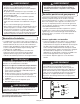
3. Using a screwdriver, remove the self-tapping screws
holding the burner clamps beneath the case and
remove the burner. (Fig. 40)
4. Look inside lower end of venturi tube for nests, webs or
mud. If present, clean as noted in Step 1, Fig. 38.
5. Inspect and clean the burner if needed.
6. Replace the burner and burner clamps, and position the
burner in the operating position.
7. Make sure the orifice fittings are inside the venturi tube,
then tighten all self tapping screws. (Fig. 41 and Fig. 42)
Fig. 39
Fig. 40
Burner
Orifice Fitting
Orifice Fitting in Venturi Tube
Venturi
Tube
Fig. 41